Nissan Juke Service and Repair Manual : Back door opener system
System Diagram
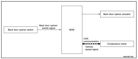
System Description
BACK DOOR OPENER OPERATION
When back door opener switch is pressed, BCM operates back door opener actuator.
NOTE
:
Back door opener actuator is not for locking the back door. The function is only
to open the back door.
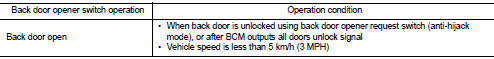
OPERATION CONDITION
If the following conditions are satisfied, back door opener operation is performed.
NOTE
:
ŌĆó When battery terminal is disconnected and reconnected during all doors unlock
state, back door may not
open.
ŌĆó Regardless of door lock actuator state, BCM resets recognition of all doors unlock state approximately 30 seconds after battery terminal is disconnected and BCM recognizes that all doors are in lock state.
ŌĆó When battery terminal is reconnected and back door does not open, have BCM recognize that all doors are in unlock state.
 System (intelligent key system)
Intelligent key system : System Diagram
Intelligent key system : System Description
ŌĆó The Intelligent Key system is a system that makes it possible to lock and
unlock the door locks (door lock ...
 Diagnosis system (BCM)
Common item : consult-III Function (BCM - COMMON ITEM)
APPLICATION ITEM
CONSULT-III performs the following functions via CAN communication with BCM.
SYSTEM APPLICATION
BCM can perform the follow ...
Other materials:
BCM (body control module)
Removal and Installation
CAUTION:
Before replacing BCM, perform ŌĆ£READ CONFIGURATIONŌĆØ to save or print current
vehicle specification.
Refer to BCS-150, "Description".
REMOVAL (RHD MODELS)
1. Remove glove box assembly. Refer to IP-13, "Removal and Installation".
2. Re ...
Heated seat switches
Front
To ensure maximum comfort during colder weather, the front seats and the available rear outboard seats in your Nissan Leaf are equipped with sophisticated built-in heating elements. The control switches, conveniently located on the center console and positioned a ...
Fuel pressure check
Work Procedure
FUEL PRESSURE RELEASE
1.FUEL PRESSURE RELEASE
With CONSULT-III
1. Turn ignition switch ON.
2. Perform ŌĆ£FUEL PRESSURE RELEASEŌĆØ in ŌĆ£WORK SUPPORTŌĆØ mode with CONSULT-III.
3. Start engine.
4. After engine stalls, crank it two or three times to release all fuel
pressure.
5 ...
