Nissan Juke Service and Repair Manual : Diagnosis system (BCM)
Common item : consult-III Function (BCM - COMMON ITEM)
APPLICATION ITEM
CONSULT-III performs the following functions via CAN communication with BCM.
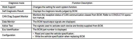
SYSTEM APPLICATION
BCM can perform the following functions for each system.
NOTE
:
It can perform the diagnosis modes except the following for all sub system
selection items.
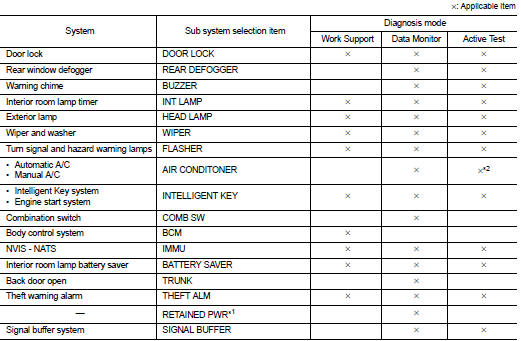
NOTE
:
• *1: This item is displayed, but not used.
• *2: For models with automatic A/C, this diagnosis mode is not used.
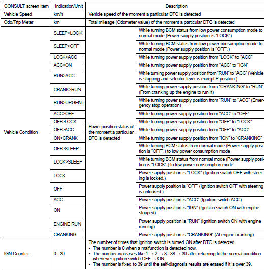
FREEZE FRAME DATA (FFD)
The BCM records the following vehicle condition at the time a particular DTC is detected, and displays on CONSULT-III.
Door lock : consult-III Function (BCM - DOOR LOCK) (With Super Lock)
BCM CONSULT-III FUNCTION
CONSULT-III performs the following functions via CAN communication with BCM.
WORK SUPPORT
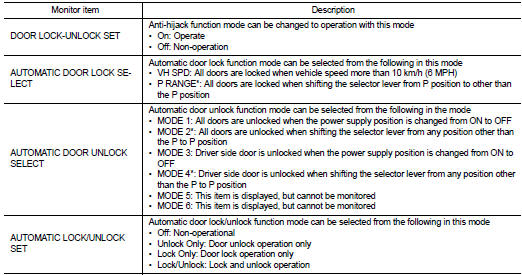
*: P range interlock door lock can be selected for M/T models, but automatic door lock/unlock function does not operate.
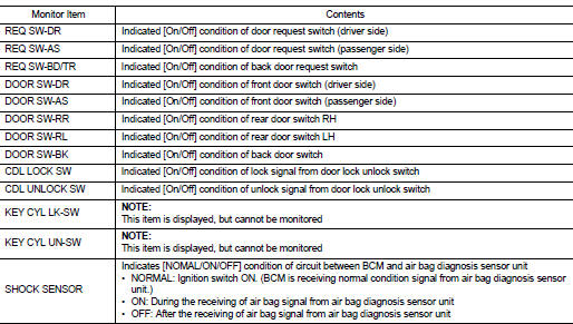
DATA MONITOR
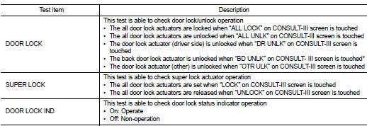
ACTIVE TEST
*: BD UNLK function does not operate.
Intelligent key : consult-III Function (BCM - INTELLIGENT KEY) (With Super Lock)
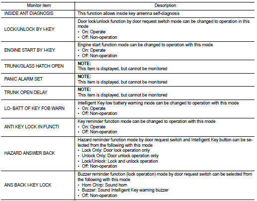
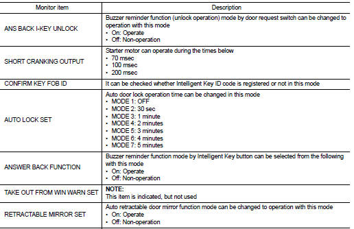
WORK SUPPORT
SELF-DIAG RESULT
Refer to BCS-67, "DTC Index".
DATA MONITOR
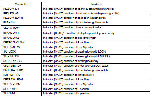
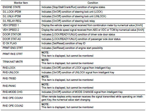
*1: It is displayed but does not operate on CVT models.
*2: OFF is displayed when brake pedal is depressed while brake switch power supply is OFF.
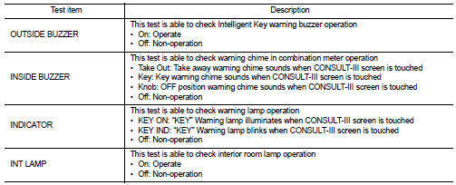
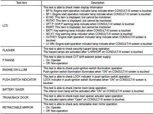
ACTIVE TEST
Trunk : consult-III Function (BCM - TRUNK) (With Super Lock)
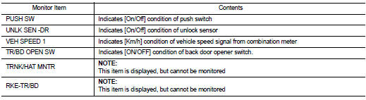
DATA MONITOR
 Back door opener system
System Diagram
System Description
BACK DOOR OPENER OPERATION
When back door opener switch is pressed, BCM operates back door opener
actuator.
NOTE:
Back door opener actuator is not for lock ...
 ECU diagnosis information
BCM
List of ECU Reference
...
Other materials:
Engine knock
Description
CHART 16: ENGINE KNOCK
Diagnosis Procedure
1.CHECK ENGINE OIL
Check the grade of engine oil. Refer to LU-33, "Inspection".
Is the inspection result normal?
YES >> GO TO 2.
NO >> Replace engine oil. Refer to LU-34, "Refilling".
2.CHECK ENGINE ...
Seat belt buckle switch signal circuit (passenger side)
Diagnosis Procedure
1.CHECK SEAT BELT BUCKLE SWITCH (PASSENGER SIDE) CIRCUIT
1. Turn ignition switch OFF.
2. Disconnect combination meter connector and seat belt buckle switch (passenger
side) connector.
3. Check continuity between combination meter harness connector and seat belt
buckle swi ...
Removal and Installation
CAUTION:
• Be sure to use genuine exhaust system parts or equivalents which are specially
designed for heat
resistance, corrosion resistance and shape.
• Perform the operation with the exhaust system fully cooled down because the
system is still hot just
after the engine stops.
• Be c ...
