Nissan Juke Service and Repair Manual : P0226 APP sensor
DTC Logic
DTC DETECTION LOGIC
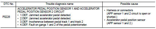
Diagnosis Procedure
1.CHECK GROUND CONNECTIONS
1. Turn ignition switch OFF.
2. Check ground connection E38. Refer to Ground inspection in GI-44, "Circuit Inspection".
Is the inspection result normal? YES >> GO TO 2.
NO >> Repair or replace ground connection.
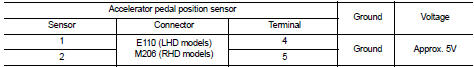
2.CHECK ACCELERATOR PEDAL POSITION SENSOR POWER SUPPLY CIRCUIT
1. Disconnect accelerator pedal position sensor harness connector.
2. Turn ignition switch ON.
3. Check the voltage between accelerator pedal position sensor connector and ground.
Is the inspection result normal? YES >> GO TO 4.
NO >> GO TO 3.
3.DETECT MALFUNCTIONING PART
ŌĆó Harness connectors M77, E105 (RHD models) ŌĆó Harness connectors M95, M202 (RHD models) ŌĆó Harness for open or short between ECM and accelerator pedal position sensor
>> Repair open circuit or short to ground or short to power in harness or connector.
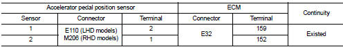
4.CHECK ACCELERATOR PEDAL POSITION SENSOR GROUND CIRCUIT FOR OPEN AND SHORT
1. Turn ignition switch OFF.
2. Disconnect ECM harness connector.
3. Check the continuity between accelerator pedal position sensor harness connector and ECM harness connector.
4. Also check harness for short to ground and short to power.
Is the inspection result normal? YES >> GO TO 6.
NO >> GO TO 5.
5.DETECT MALFUNCTIONING PART
ŌĆó Harness connectors M77, E105 (RHD models) ŌĆó Harness connectors M95, M202 (RHD models) ŌĆó Harness for open or short between ECM and accelerator pedal position sensor
>> Repair open circuit or short to ground or short to power in harness or connector.
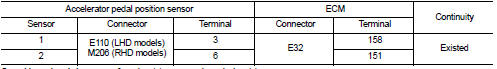
6.CHECK ACCELERATOR PEDAL POSITION SENSOR INPUT SIGNAL CIRCUIT FOR OPEN AND SHORT
1. Check the continuity between accelerator pedal position sensor harness connector and ECM harness connector.
2. Also check harness for short to ground and short to power.
Is the inspection result normal? YES >> GO TO 8.
NO >> GO TO 7.
7.DETECT MALFUNCTIONING PART
ŌĆó Harness connectors M77, E105 (RHD models) ŌĆó Harness connectors M95, M202 (RHD models) ŌĆó Harness for open or short between ECM and accelerator pedal position sensor
>> Repair open circuit or short to ground or short to power in harness or connector.
8.CHECK ACCELERATOR PEDAL POSITION SENSOR
Refer to EC-929, "Component Inspection".
Is the inspection result normal? YES >> GO TO 9.
NO >> Replace accelerator pedal position sensor.
9.CHECK INTERMITTENT INCIDENT
Refer to GI-42, "Intermittent Incident", ???INCIDENT SIMULATION TESTS??? and ???GROUND INSPECTION???.
>> INSPECTION END
Component Inspection
1.CHECK ACCELERATOR PEDAL POSITION SENSOR
1. Turn ignition switch OFF.
2. Disconnect accelerator pedal position sensor harness connector.
3. Check resistance between accelerator pedal position sensor as follows.
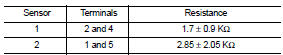
Is the inspection result normal? YES >> INSPECTION END
NO >> Replace accelerator pedal position sensor
 P0225 APP sensor
DTC Logic
DTC DETECTION LOGIC
NOTE:
ŌĆó If DTC P0225 is displayed with DTC P0641, first perform trouble diagnosis for
DTC P0641. Refer to
EC-974, "DTC Logic".
Diagnosis Procedure
1 ...
 P0263, P0266, P0269, P0272 fuel injector
DTC Logic
DTC DETECTION LOGIC
NOTE:
Check injector code when the above DTC is indicated. If the code is normal,
replace injector showing an applicable
code. If the code is not normal, load inj ...
Other materials:
Seats
WARNING
Never ride in a moving vehicle with the seatback significantly reclined. This practice is extremely dangerous. When a seat is reclined, the shoulder belt cannot maintain proper contact with your body; in the event of a collision, you could be forcefully t ...
Precaution Necessary for Steering Wheel Rotation after Battery Disconnect
NOTE:
ŌĆó Before removing and installing any control units, first turn the ignition
switch to the LOCK position, then disconnect
both battery cables.
ŌĆó After finishing work, confirm that all control unit connectors are connected
properly, then re-connect both
battery cables.
ŌĆó Always us ...
General Precautions
WARNING:
When replacing fuel line parts, be sure to observe the following.
ŌĆó Put a ???CAUTION: FLAMMABLE??? sign in the workshop.
ŌĆó Be sure to work in a well ventilated area and furnish workshop with a CO2 fire
extinguisher.
ŌĆó Never smoke while servicing fuel system. Keep open flames a ...
