Nissan Juke Service and Repair Manual : Fluid cooler system
Exploded View
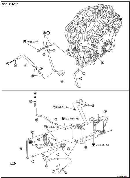
1. Copper washer
2. CVT fluid cooler tube
3. Hose clamp
4. Fluid cooler hose A
5. Fluid cooler tube
6. Fluid cooler hose B
7. Fluid cooler hose C
8. Transaxle assembly
9. Fluid cooler hose D
10. Fluid cooler hose E
11. Fluid cooler hose F
12. Bypass valve
13. Fluid cooler
14. Air guide
15. Bracket A
16. Bracket B
A. To radiator
 : Vehicle side
Removal and Installation
REMOVAL
1. Remove engine under cover.
2. Remove front bumper assembly. Refer to EXT-13, "Removal and Installation".
3. Remove air guide from fluid cooler.
4. Remove fluid cooler hose E and fluid cooler hose F.
5. Remove fluid cooler.
6. Remove air duct (inlet). Refer to EM-26, "Removal and Installation".
7. Remove fluid cooler hose C and fluid cooler hose D.
8. Remove bypass valve from bracket B.
9. Remove fluid cooler hose A and fluid cooler hose B.
10. Remove fluid cooler tube.
11. Remove bracket A and bracket B.
12. Remove CVT fluid cooler tube from transaxle assembly.
INSTALLATION
Note the following, and install in the reverse order of removal.
CAUTION:
Never reuse copper washer.
• When installing CVT fluid cooler tube (1) to transaxle assembly: - Contact CVT fluid cooler tube a boss portion (A) of the transaxle case.
- Tighten the bolt of CVT fluid cooler tube without moving the CVT fluid cooler tube
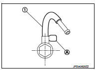
• Refer to the followings when installing fluid cooler hose.
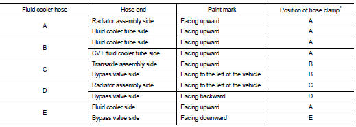
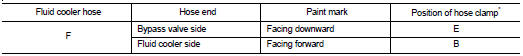
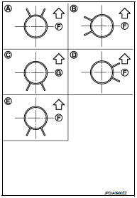
*: Refer to the illustrations for the specific position each hose clamp tab.
- The illustrations indicate the view from the hose ends.
F : Vehicle upper
 G : Vehicle front
- When installing hose clamps center line of each hose clamp tab should be positioned as shown in the figure.
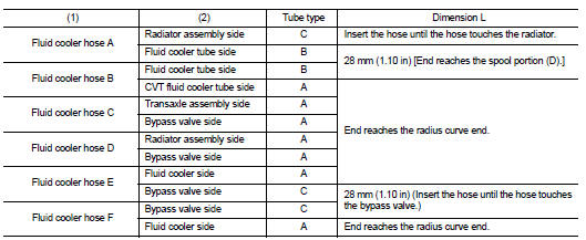
- Insert fluid cooler hose according to dimension (L) described below.
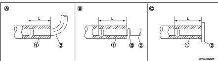
- Set hose clamps (1) at the both ends of fluid cooler hose (2) with dimension (A) from the hose edge.
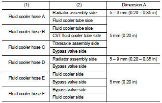
- Hose clamp should not interfere with the bulge of fluid cooler tube.
Inspection
INSPECTION AFTER INSTALLATION
Check for CVT fluid leakage and CVT fluid level. Refer to TM-184, "Inspection".
 Water hose
Exploded View
1. Hose clamp
2. Water hose
A. Water outlet
B. Oil warm
Removal and Installation
REMOVAL
WARNING:
Never remove the radiator cap when the engine is hot. Serious burns could oc ...
 Unit removal and installation
Transaxle assembly
Exploded View
1. CVT fluid level gauge
2. CVT fluid charging pipe
3. O-ring
4. Transaxle assembly
5. Air breather hose
A. For tightening torque, refer to TM-301, "R ...
Other materials:
Additional service when replacing ECM
Description
When replacing ECM, this procedure must be performed.
Work Procedure
1.PERFORM INITIALIZATION OF NATS SYSTEM AND REGISTRATION OF ALL NATS
IGNITION KEY IDS
Refer to SEC-50, "BCM : Special Repair Requirement" (With intelligent key
system), SEC-190, "BCM : Work
Proce ...
Performance test
Inspection
INSPECTION PROCEDURE
1. Connect recovery/recycling/recharging equipment (for HFC-134a) or manifold
gauge.
2. Start the engine, and set to the following condition.
Test condition
3. Maintain test condition until A/C system becomes stable. (Approximately 10
minutes)
4. Check t ...
P0520 EOP sensor
DTC Logic
DTC CONFIRMATION PROCEDURE
1.PRECONDITIONING
If DTC Confirmation Procedure has been previously conducted, always perform
the following procedure
before conducting the next test.
1. Turn ignition switch OFF and wait at least 10 seconds.
2. Turn ignition switch ON.
3. Turn ignitio ...
