Nissan Juke Service and Repair Manual : P1701 TCM
DTC Logic
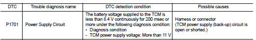
DTC DETECTION LOGIC
DTC CONFIRMATION PROCEDURE
1.PREPARATION BEFORE WORK
If another "DTC CONFIRMATION PROCEDURE" occurs just before, turn ignition switch OFF and wait for at least 10 seconds, then perform the next test.
>> GO TO 2.
2.CHECK DTC DETECTION
1. Start the engine and wait for 5 seconds or more.
2. Check the first trip DTC.
Is ŌĆ£P1701ŌĆØ detected? YES >> Go to TM-440, "Diagnosis Procedure".
NO >> INSPECTION END
Diagnosis Procedure
1.CHECK TCM POWER SUPPLY (BACK-UP) CIRCUIT
1. Turn ignition switch OFF.
2. Disconnect the TCM connector.
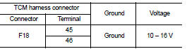
3. Check the voltage between the TCM harness connector terminals and ground.
Is the inspection result normal? YES >> Check intermittent incident. Refer to GI-42, "Intermittent Incident".
NO >> GO TO 2.
2.DETECTION OF MALFUNCTION ITEMS
Check the following items: ŌĆó Open or short circuit of the harness between battery positive terminal and TCM connectors terminals 45 and 46. Refer to PG-10, "Wiring Diagram - BATTERY POWER SUPPLY -".
ŌĆó 10A fuse (No.33, fuse and fusible link block). Refer to PG-23, "Fuse and Fusible Link Arrangement".
ŌĆó 10A fuse (No.36, fuse and fusible link block). Refer to PG-23, "Fuse and Fusible Link Arrangement".
Is the inspection result normal? YES >> Check intermittent incident. Refer to GI-42, "Intermittent Incident".
NO >> Repair or replace the malfunctioning parts.
 P1588 G sensor
DTC Logic
DTC DETECTION LOGIC
DTC CONFIRMATION PROCEDURE
CAUTION:
Be careful of the driving speed.
1.PREPARATION BEFORE WORK
If another "DTC CONFIRMATION PROCEDURE" occurs just befor ...
 P1739 1GR incorrect ratio
DTC Logic
DTC DETECTION LOGIC
DTC CONFIRMATION PROCEDURE
CAUTION:
ŌĆó Be sure to perform ŌĆ£TM-442, "Diagnosis Procedure"ŌĆØ and then perform ŌĆ£DTC
CONFIRMATION PROCEDUREŌĆØ.
ŌĆó N ...
Other materials:
Vehicle does not enter 4WD mode
Description
Vehicle does not enter 4-wheel drive mode even though 4WD warning lamp turned
to OFF.
Diagnosis Procedure
1.CHECK 4WD WARNING LAMP
Turn the ignition switch ON.
Does 4WD warning lamp turn ON?
YES >> GO TO 2.
NO >> Proceed to diagnosis procedure. Refer to DLN-80, & ...
Diagnosis system (TCM)
CONSULT-III Function (TRANSMISSION)
CONSULT-III can display each diagnostic item using the diagnostic test modes
shown below.
FUNCTION
*: ŌĆ£Function TestŌĆØ can be selected, but do not use it.
WORK SUPPORT MODE
Display Item List
Engine Brake Adjustment
ŌĆ£ENGINE BRAKE LEVELŌĆØ
0: ...
ECU diagnosis information
4WD control module
Reference Value
VALUES ON THE DIAGNOSIS TOOL
TERMINAL LAYOUT
PHYSICAL VALUES
*: The values are changed by throttle opening and engine speed.
CAUTION:
When using circuit tester to measure voltage for inspection, be sure not to
extend forcibly any connector
t ...
