Nissan Juke Service and Repair Manual : P1588 G sensor
DTC Logic
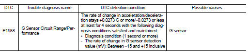
DTC DETECTION LOGIC
DTC CONFIRMATION PROCEDURE
CAUTION:
Be careful of the driving speed.
1.PREPARATION BEFORE WORK
If another "DTC CONFIRMATION PROCEDURE" occurs just before, turn ignition switch OFF and wait for at least 10 seconds, then perform the next test.
>> GO TO 2.
2.CHECK DTC DETECTION
 With CONSULT-III
1. Start the engine.
2. Select “Data Monitor” in “TRANSMISSION”.
3. Select “G SPEED”.
4. Drive the vehicle.
5. Maintain the following conditions for 5 seconds or more.
Selector lever : “D” position G SPEED : 0.05 G or more
6. Stop the vehicle.
7. Check the DTC.
Is “P1588” detected? YES >> Go to TM-438, "Diagnosis Procedure".
NO >> INSPECTION END
Diagnosis Procedure
1.CHECK G SENSOR SIGNAL
 With CONSULT-III
1. Park the vehicle on a level surface.
2. Turn ignition switch ON.
3. Select “Data Monitor” in “TRANSMISSION”.
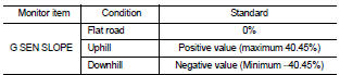
4. Select “G SEN SLOPE”.
5. Swing the vehicle and check if the value varies between −40.45% and 40.45%.
Is the inspection result normal?
YES >> GO TO 2.
NO >> GO TO 3.
2.G SENSOR CALIBRATION (PART 1)
 With CONSULT-III
1. Select “Self Diagnostic Results” in “TRANSMISSION”.
2. Touch “Erase”.
>> Perform "G SENSOR CALIBRATION". Refer to TM-377, "Procedure".
3.CHECK G SENSOR
1. Remove the G sensor. TM-492, "Removal and Installation".
2. Connect the all connectors.
3. Turn ignition switch ON.
4. Check the voltage between TCM connector terminal and ground.
 : Direction of gravitational
force
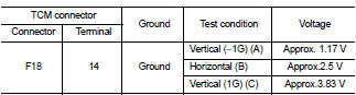
Is the inspection result normal? YES >> GO TO 4.
NO >> Replace G sensor.TM-492, "Removal and Installation".
4.G SENSOR CALIBRATION (PART 2)
 With CONSULT-III
1. Install G sensor. TM-492, "Removal and Installation".
2. Select “Self Diagnostic Results” in “TRANSMISSION”.
3. Touch “Erase”.
>> Perform "G SENSOR CALIBRATION". Refer to TM-377, "Procedure".
 P1586 G sensor
DTC Logic
DTC DETECTION LOGIC
DTC CONFIRMATION PROCEDURE
CAUTION:
Be careful of the driving speed.
1.PREPARATION BEFORE WORK
If another "DTC CONFIRMATION PROCEDURE" occurs just befor ...
 P1701 TCM
DTC Logic
DTC DETECTION LOGIC
DTC CONFIRMATION PROCEDURE
1.PREPARATION BEFORE WORK
If another "DTC CONFIRMATION PROCEDURE" occurs just before, turn ignition
switch OFF and wait for a ...
Other materials:
P0122, P0123 TP SENSOR
DTC Logic
DTC DETECTION LOGIC
NOTE:
If DTC P0122 or P0123 is displayed with DTC P0643, first perform the trouble
diagnosis for DTC P0643.
Refer to EC-686, "DTC Logic".
DTC CONFIRMATION PROCEDURE
1.PRECONDITIONING
If DTC Confirmation Procedure has been previously conducted, alw ...
Removal and Installation
REMOVAL
1. Separate the rear propeller shaft. Refer to DLN-121, "Removal and
Installation".
2. Remove right side drive shaft. Refer to FAX-24, "RIGHT SIDE : Removal and
Installation".
3. Remove catalyst convertor support bracket (RH). EM-35, "4WD : Removal and
Insta ...
Removal and installation
MULTI DISPLAY UNIT
Exploded View
REMOVAL
Refer to IP-12, "Exploded View".
DISASSEMBLY
1. Silencer tape
2. Multi display unit
3. Silencer tape
4. Clip
5. Control finisher
Removal and Installation
REMOVAL
Refer to IP-12, "Exploded View".
CAUTION:
• When per ...
