Nissan Juke Service and Repair Manual : CSC (concentric slave cylinder)
Exploded View
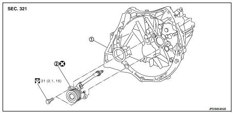
1. Transaxle assembly 2. CSC (Concentric Slave Cylinder)
 : Always replace after every
disassembly.
 : N·m (kg-m, ft-lb)
Removal and Installation
CAUTION:
• Never reuse CSC (Concentric Slave Cylinder). Because CSC slides back to the
original position
every time when removing transaxle assembly. At this timing, dust on the sliding
parts may damage
a seal of CSC and may cause clutch fluid leakage.
• Never disassemble CSC.
• Keep painted surface on the body or other parts free of clutch fluid. If it spills, wipe up immediately and wash the affected area with water.
REMOVAL
1. Remove transaxle assembly. Refer to TM-30, "Removal and Installation" (RS5F92R), or TM-84, "MR16DDT : Removal and Installation" (RS6F94R with MR16DDT), TM-86, "K9K : Removal and Installation" (RS6F94R with K9K).
2. Remove CSC from clutch housing.
INSTALLATION
1. Install CSC to clutch housing, and then tighten CSC mounting bolts to the specified torque.
CAUTION:
• Never reuse CSC.
• Never insert and operate CSC because piston and stopper of CSC components may fall off.
2. For the next step and after, install in the reverse order of removal.
Inspection and Adjustment
INSPECTION AFTER INSTALLATION
Check the fluid leakage and the fluid level. Refer to CL-10, "RS5F92R : Inspection" (RS5F92R) or CL-13, "RS6F94R : Inspection" (RS6F94R).
ADJUSTMENT AFTER INSTALLATION
Perform the air bleeding. Refer to CL-12, "RS5F92R : Air Bleeding" (RS5F92R) or CL-15, "RS6F94R : Air Bleeding" (RS6F94R).

 Clutch disc and clutch cover
Except for K9K : Exploded View
HR16DE
1. Flywheel
2. Clutch disc
3. Clutch cover
4. Input shaft
A. First step
B. Final step
: N·m (kg-m, ft-lb)
: Apply lithium-based grease
including ...
Other materials:
Steering does not lock
Description
Steering does not lock when door is open while ignition switch is OFF.
NOTE:
Before performing the diagnosis, check “Work Flow”. Refer to SEC-47, "Work
Flow".
Diagnosis Procedure
1.CHECK DOOR SWITCH
Check door switch.
Refer to DLK-87, "Component Function C ...
Handling precaution
Nissan Dynamic Control System
• The engine torque, engine power, boost, and instantaneous fuel consumption
are provided for information
purposes only. They are not intended to prompt the driver to adjust driving
style. The readings may be
slightly delayed relative to the actual vehicle beha ...
P0335 CKP sensor (POS)
DTC Logic
DTC DETECTION LOGIC
DTC CONFIRMATION PROCEDURE
1.PRECONDITIONING
If DTC Confirmation Procedure has been previously conducted, always turn
ignition switch OFF and wait at
least 10 seconds before conducting the next test.
TESTING CONDITION:
Before performing the following proced ...
