Nissan Juke Service and Repair Manual : 4WD control module
Removal and Installation
REMOVAL
1. Turn the ignition switch OFF.
2. Remove front (left side) seat. Refer to SE-27, "Removal and Installation".
3. Remove floor carpet. Refer to INT-23, "Removal and Installation".
4. Remove G sensor. Refer to TM-282, "Removal and Installation".
5. Disconnect 4WD control module harness connector.
6. Remove 4WD control module mounting nuts.
7. Remove 4WD control module.
INSTALLATION
Note the following, and install in the reverse order of removal.
• Perform “G SENSOR CALIBRATION”. Refer to TM-182, "Description".
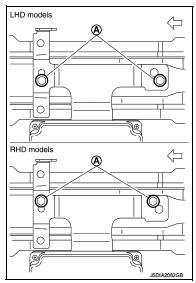
• When installing 4WD control module, install it following procedure.
1. Align the securing holes (A) of bracket as shown in the figure and temporarily tighten mounting bolts.
 : Vehicle front
2. When replace 4WD control module, hold 4WD control module and remove protector paper on the adhesion area of bracket to bond to the front floor (LH).
3. Tighten mounting bolts to the specified torque.
Tightening torque : 8.0 N·m (0.82 kg-m, 71in-lb)
• When replacing 4WD control module, perform writing unit parameter.
Refer to DLN-39, "Work Procedure".

 4WD mode switch
Removal and Installation
REMOVAL
1. Remove instrument lower panel. Refer to IP-12, "Exploded View".
2. Remove 4WD mode switch.
INSTALLATION
Install in the reverse order of removal. ...
Other materials:
Eco information
CAUTION
Do not adjust the display controls while driving so that full attention may
given to vehicle operation.
The following ECO INFO mode will appear on the display by pushing the ECO information
button, then turning the selection dial to scroll through the different screens.
While driving, ...
B2098 ignition relay on stuck
Description
• IPDM E/R operates the ignition relay when it receives an ignition switch ON
signal from BCM via CAN communication.
• Turn the ignition relay OFF by pressing the push-button ignition switch once
when the vehicle speed is 4 km/
h (2.5 MPH) or less.
• Turn the ignition relay ...
Fuel level sensor unit, fuel filter and fuel pump assembly
Exploded View
1. Fuel tank
2. Rock ring
3.
Fuel level sensor unit, fuel filter and
fuel pump assembly
4. O-ring
: Vehicle front
: Always replace after every
disassembly.
: N·m (kg-m, ft-lb)
1. Fuel filter and fuel pump assembly
2. Fuel gauge
Removal and Installation
WARNING: ...
