Nissan Juke Service and Repair Manual : Clutch pedal
LHD : Exploded View
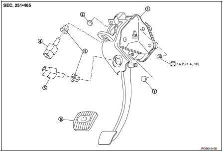
1. Clutch pedal
2. Stopper rubber
3. Clip
4. Clutch interlock switch *1
5. Clutch pedal position switch *2
6. Pedal pad
7. Pedal stopper rubber
*1 : With push-button ignition switch system *2 : With ASCD or with push-button ignition switch system
 : N·m (kg-m, ft-lb)
LHD : Removal and Installation
REMOVAL
1. Remove instrument lower panel LH. (MR16DDT) Refer to IP-13, "Removal and Installation".
2. Disconnect clutch pedal position switch connector. (With ASCD or with
push-button ignition switch system)
3. Disconnect clutch interlock switch connector. (With push-button ignition
switch system)
4. Disconnect clip of harness from clutch pedal. (With ASCD or with push-button
ignition switch system)
5. Remove master cylinder rod end from clutch pedal.
6. Remove clutch pedal position switch and clip from clutch pedal.
(With ASCD or with push-button ignition switch system) 7. Remove clutch interlock switch and clip from clutch pedal. (With push-button ignition switch system) 8. Remove clutch pedal from the vehicle.
9. Remove pedal pad from clutch pedal.
10. Remove stopper rubber and pedal stopper rubber from clutch pedal, using a suitable remover.
INSTALLATION
Note the following, and install in the reverse order of removal.
CAUTION:
Press master cylinder rod end into clutch pedal until it stops.
LHD : Inspection and Adjustment
INSPECTION AFTER REMOVAL
• Check clutch pedal for bend, damage, or a cracked weld. If bend, damage, or a cracked weld is found, replace clutch pedal.
• Check stopper rubber and pedal stopper rubber. If damage or deformation is found, replace stopper rubber and pedal stopper rubber.
• Check pedal pad. If wear or damage is found, replace pedal pad.
INSPECTION AFTER INSTALLATION
• Check the clutch pedal height, clutch pedal height at clutch disengagement, and clutch pedal play. Refer to CL-7, "Inspection and Adjustment".
• Check the clutch interlock switch position. (With push-button ignition switch system) Refer to CL-7, "Inspection and Adjustment".
• Check the clutch pedal position switch position. (With ASCD or with push-button ignition switch system) Refer to CL-7, "Inspection and Adjustment".
ADJUSTMENT AFTER INSTALLATION
• Adjust the clutch interlock switch position. (With push-button ignition switch system) Refer to CL-7, "Inspection and Adjustment".
• Adjust the clutch pedal position switch position. (With ASCD or with push-button ignition switch system) Refer to CL-7, "Inspection and Adjustment".
RHD
RHD : Exploded View
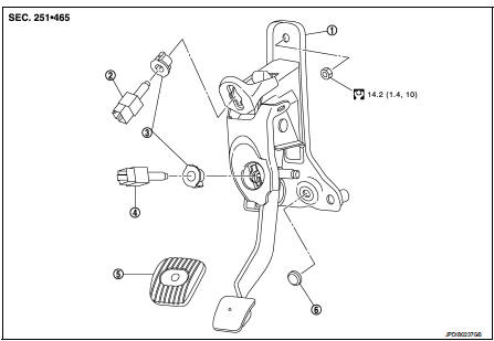
1. Clutch pedal
2. Clutch interlock switch *1
3. Clip
4. Clutch pedal position switch *2
5. Pedal pad
6. Pedal stopper rubber
*1 : With push-button ignition switch system *2 : With ASCD or with push-button ignition switch system
 : N·m (kg-m, ft-lb)
RHD : Removal and Installation
REMOVAL
1. Disconnect clutch pedal position switch connector. (With ASCD or with
push-button ignition switch system)
2. Disconnect clutch interlock switch connector. (With push-button ignition
switch system)
3. Disconnect clip of harness from clutch pedal. (With ASCD or with push-button
ignition switch system)
4. Remove master cylinder rod end from clutch pedal.
5. Remove clutch pedal position switch and clip from clutch pedal. (With ASCD or with push-button ignition switch system) 6. Remove clutch interlock switch and clip from clutch pedal. (With push-button ignition switch system) 7. Remove clutch pedal from the vehicle.
8. Remove pedal pad from clutch pedal.
9. Remove pedal stopper rubber from clutch pedal, using a suitable remover.
INSTALLATION
Note the following, and install in the reverse order of removal.
CAUTION
:
Press master cylinder rod end into clutch pedal until it stops.
RHD : Inspection and Adjus
INSPECTION AFTER REMOVAL
• Check clutch pedal for bend, damage, or a cracked weld. If bend, damage, or a cracked weld is found, replace clutch pedal.
• Check pedal stopper rubber. If damage or deformation is found, replace pedal stopper rubber.
• Check pedal pad. If wear or damage is found, replace pedal pad.
INSPECTION AFTER INSTALLATION
• Check the clutch pedal height, clutch pedal height at clutch disengagement, and clutch pedal play. Refer to CL-7, "Inspection and Adjustment".
• Check the clutch interlock switch position. (With push-button ignition switch system) Refer to CL-7, "Inspection and Adjustment".
• Check the clutch pedal position switch position. (With ASCD or with push-button ignition switch system) Refer to CL-7, "Inspection and Adjustment".
ADJUSTMENT AFTER INSTALLATION
• Adjust the clutch interlock switch position. (With push-button ignition switch system) Refer to CL-7, "Inspection and Adjustment".
• Adjust the clutch pedal position switch position. (With ASCD or with push-button ignition switch system) Refer to CL-7, "Inspection and Adjustment".

 Clutch master cylinder
LHD : Exploded View
1. Reservoir hose
2. Reservoir tank
3. Master cylinder
LHD : Removal and Installation
REMOVAL
CAUTION:
• Keep painted surface on the body or other parts free of clutch ...
Other materials:
P1651 starter motor relay
Description
ECM controls ON/OFF state of the starter relay, according to the engine and
vehicle condition. Models with no
Intelligent Key System transmit a control signal directly to IPDM E/R. On the
other hand, models with the Intelligent
Key System transmit a control signal to IPDM E/R by w ...
Radiator core support
HR16DE
HR16DE : Exploded View
1. Radiator core support upper
2. Air guide RH (MT models)
3. Radiator core support lower
4. Air guide LH 5. Air guide (upper)
6. Air guide LH (CVT models)
7. Air guide RH (CVT models)
: N·m (kg-m, ft-lb)
HR16DE : Removal and Installation
RADIATOR CORE S ...
Symptom diagnosis
NOISE, VIBRATION AND HARSHNESS
(NVH) TROUBLESHOOTING
NVH troubleshooting Chart
1. Locate the area where noise occurs.
2. Confirm the type of noise.
3. Specify the operating condition of engine
4. Check specified noise source.
If necessary, repair or replace these parts.
A: Closely rela ...
