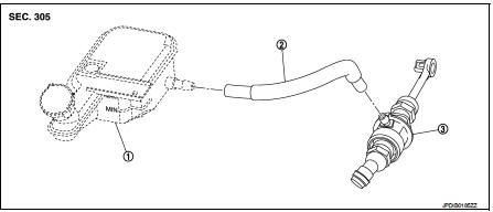
Nissan Juke Service and Repair Manual : Clutch master cylinder
LHD : Exploded View
1. Reservoir hose
2. Reservoir tank
3. Master cylinder
LHD : Removal and Installation
REMOVAL
CAUTION:
• Keep painted surface on the body or other parts free of clutch fluid. If it
spills, wipe up immediately
and wash the affected area with water.
• Never disassemble clutch master cylinder.
1. Drain clutch fluid. Refer to CL-10, "RS5F92R : Draining" (RS5F92R) or CL-13, "RS6F94R : Draining" (RS6F94R).
2. Remove air cleaner case. Refer to EM-26, "Removal and Installation" (MR16DDT), EM-161, "Removal and Installation" (HR16DE), or EM-280, "Removal and Installation" (K9K).
3. Remove reservoir hose from reservoir tank and master cylinder.
4. Remove master cylinder rod end (
) from clutch pedal.
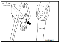
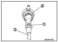
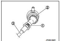
5. Pull up the lock pin (1) from connector of master cylinder (2) and separate clutch tube (3).
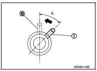
6. Rotate master cylinder clockwise by 45 degrees, and then remove master cylinder from the vehicle.
INSTALLATION
CAUTION:
Keep painted surface on the body or other parts free of clutch fluid. If it
spills, wipe up immediately
and wash the affected area with water.
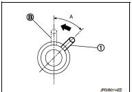
1. Tilt master cylinder clockwise by 45 degrees (A) and insert it to the mounting hole. Rotate counterclockwise and secure it. At this time, nipple (1) is upward of the vehicle.
B : Mounting condition
2. Install master cylinder rod end to clutch pedal.
CAUTION:
Press master cylinder rod end into clutch pedal until it
stops.
3. Install reservoir hose to reservoir tank and master cylinder.
CAUTION:
Set reservoir hose with painted mark facing upward.
4. Press down the lock pin into connector of master cylinder until it stops.
5. Install clutch tube into connector of master cylinder until it stops.
6. For the next step and after, install in the reverse order of removal.
LHD : Inspection and Adjustment
INSPECTION AFTER INSTALLATION
• Check the fluid leakage and the fluid level. Refer to CL-10, "RS5F92R : Inspection" (RS5F92R) or CL-13, "RS6F94R : Inspection" (RS6F94R).
• Check the clutch pedal height, clutch pedal height at clutch disengagement, and clutch pedal play. Refer to CL-7, "Inspection and Adjustment".
• Check the clutch interlock switch position. (With push-button ignition switch system) Refer to CL-7, "Inspection and Adjustment".
• Check the clutch pedal position switch position. (With ASCD or with push-button ignition switch system) Refer to CL-7, "Inspection and Adjustment".
ADJUSTMENT AFTER INSTALLATION
• Adjust the clutch interlock switch position. (With push-button ignition switch system) Refer to CL-7, "Inspection and Adjustment".
• Adjust the clutch pedal position switch position. (With ASCD or with push-button ignition switch system) Refer to CL-7, "Inspection and Adjustment".
• Perform the air bleeding. Refer to CL-12, "RS5F92R : Air Bleeding" (RS5F92R) or CL-15, "RS6F94R : Air Bleeding" (RS6F94R).
RHD
RHD : Exploded View
1. Reservoir tank
2. Reservoir hose
3. Master cyl
RHD : Removal and Installation
REMOVAL
CAUTION:
• Keep painted surface on the body or other parts free of clutch fluid. If it
spills, wipe up immediately
and wash the affected area with water.
• Never disassemble clutch master cylinder.
1. Drain clutch fluid. Refer to CL-10, "RS5F92R : Draining" (RS5F92R) or CL-13, "RS6F94R : Draining" (RS6F94R).
2. Move the fuel feed tube and the fuel return hose aside not to interfere with
work. (K9K)
3. Remove reservoir hose from reservoir tank and master cylinder.
4. Remove master cylinder rod end (
) from clutch pedal.
5. Remove the engine room insulator.
6. Remove the cowl top extension. Refer to EXT-20, "Removal and Installation".
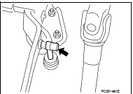
7. Pull up the lock pin (1) from connector of master cylinder (2) and separate clutch tube (3).
8. Rotate master cylinder clockwise by 45 degrees, and then remove master cylinder from the vehicle.
INSTALLATION
CAUTION
:
Keep painted surface on the body or other parts free of clutch fluid. If it
spills, wipe up immediately
and wash the affected area with water.
1. Tilt master cylinder clockwise by 45 degrees (A) and insert it to the mounting hole. Rotate counterclockwise and secure it. At this time, nipple (1) is upward of the vehicle.
B : Mounting condition
2. Install master cylinder rod end to clutch pedal.
CAUTION:
Press master cylinder rod end into clutch pedal until it
stops.
3. Install reservoir hose to reservoir tank and master cylinder.
4. Press down the lock pin into connector of master cylinder until it stops.
5. Install clutch tube into connector of master cylinder until it stops.
6. Install the fuel feed tube and the fuel return hose. (K9K) 7. Fill with clutch fluid. Refer to CL-11, "RS5F92R : Refilling" (RS5F92R) or CL-14, "RS6F94R : Refilling" (RS6F94R).
8. Install the engine room insulator.
9. Install the cowl top extension. Refer to EXT-20, "Removal and Installation".
RHD : Inspection and Adjustment
INSPECTION AFTER INSTALLATION
• Check the fluid leakage and the fluid level. Refer to CL-10, "RS5F92R : Inspection" (RS5F92R) or CL-13, "RS6F94R : Inspection" (RS6F94R).
• Check the clutch pedal height, clutch pedal height at clutch disengagement, and clutch pedal play. Refer to CL-7, "Inspection and Adjustment".
• Check the clutch interlock switch position. (With push-button ignition switch system) Refer to CL-7, "Inspection and Adjustment".
• Check the clutch pedal position switch position. (With ASCD or with push-button ignition switch system) Refer to CL-7, "Inspection and Adjustment".
ADJUSTMENT AFTER INSTALLATION
• Adjust the clutch interlock switch position. (With push-button ignition switch system) Refer to CL-7, "Inspection and Adjustment".
• Adjust the clutch pedal position switch position. (With ASCD or with push-button ignition switch system) Refer to CL-7, "Inspection and Adjustment".
• Perform the air bleeding. Refer to CL-12, "RS5F92R : Air Bleeding" (RS5F92R) or CL-15, "RS6F94R : Air Bleeding" (RS6F94R)
 Clutch pedal
LHD : Exploded View
1. Clutch pedal
2. Stopper rubber
3. Clip
4. Clutch interlock switch *1
5. Clutch pedal position switch *2
6. Pedal pad
7. Pedal stopper rubber
*1 : With push-button ...
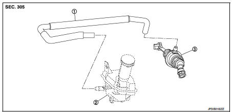
 Clutch piping
Exploded View
RS5F92R
1. CSC (Concentric Slave Cylinder)
2. Clutch tube
3. Clutch damper
4. Bracket
5. Master cylinder
RS6F94R
1. CSC (Concentric Slave Cylinder)
2. Clutch tube
3. C ...
Other materials:
Erratic acceleration
Description
CHART 10: Erratic acceleration
Diagnosis Procedure
1.CHECK ECM POWER SUPPLY AND GROUND CIRCUIT
Check ECM power supply and ground circuit. Refer to EC-885, "Diagnosis
Procedure".
Is the inspection result normal?
YES >> GO TO 2.
NO >> Repair or replace ha ...
Engine overheating
Description
CHART 17: ENGINE OVERHEATING
Diagnosis Procedure
1.CHECK COOLING SYSTEM
Check the cooling system. Refer to CO-60, "Troubleshooting Chart".
Is the inspection result normal?
YES >> GO TO 2.
NO >> Repair or replace.
2.CHECK ECM POWER SUPPLY AND GROUND CIR ...
Microphone signal circuit
Description
Power is supplied from NAVI control unit to microphone. The microphone
transmits the sound voice to the
NAVI control unit.
Diagnosis Procedure
1.CHECK CONTINUITY BETWEEN NAVI CONTROL UNIT AND MICROPHONE CIRCUIT
1. Turn ignition switch OFF.
2. Disconnect NAVI control unit connecto ...
