Nissan Juke Service and Repair Manual : Wiring diagram
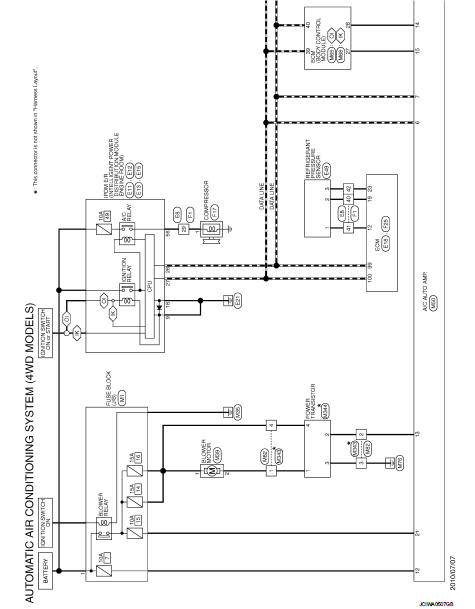
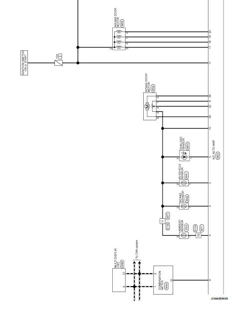
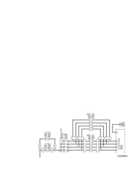
AUTOMATIC AIR CONDITIONING SYSTEM
Wiring Diagram
For connector terminal arrangements, harness layouts, and alphabets in a
 (option abbreviation; if not
described in wiring diagram), refer to GI-12, "Connector Information/Explanation
of Option Abbreviation".
 Multi display unit, BCM, ECM, IPDM E/R
List of ECU Reference
...
 Basic inspection
...
Other materials:
Fuel pump
Component Function Check
1.CHECK FUEL PUMP FUNCTION
1. Turn ignition switch ON.
2. Pinch fuel feed hose with two fingers.
Fuel pressure pulsation should be felt on the fuel feed
hose for 1 second after ignition switch is turned ON.
Is the inspection result normal?
YES >> INSPECTION END
...
Diagnosis system (BCM) (with intelligent key system)
Common item
COMMON ITEM : CONSULT-III Function (BCM - COMMON ITEM)
APPLICATION ITEM
CONSULT-III performs the following functions via CAN communication with BCM.
SYSTEM APPLICATION
BCM can perform the following functions for each system.
NOTE:
It can perform the diagnosis modes except the fo ...
How to trickle charge (AC 110-120 volt) by L1 EVSE
WARNING
If you utilize a pacemaker or an implantable cardiovascular defibrillator (ICD), ensure you maintain a minimum distance of 6 inches (15 cm) from the EVSE (Electric Vehicle Supply Equipment) at all times to prevent potential electromagnetic interference.
Before initiat ...
