Nissan Juke Service and Repair Manual : Multi display unit, BCM, ECM, IPDM E/R
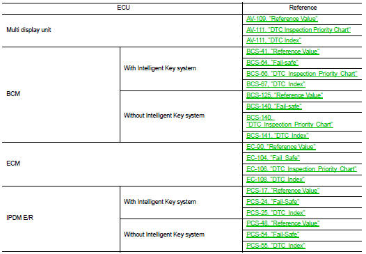
List of ECU Reference
 A/C auto AMP.
Reference Value
CONSULT-III DATA MONITOR REFERENCE VALUES
*: “DUTY” is displayed, but voltage is indicated. Or unit is not displayed
but unit is (V).
TERMINAL LAYOUT
PHYSICAL VALUES
...
 Wiring diagram
AUTOMATIC AIR CONDITIONING SYSTEM
Wiring Diagram
For connector terminal arrangements, harness layouts, and alphabets in a
(option abbreviation; if not
described in wiring diagram), refer to GI-12 ...
Other materials:
Steering switch signal B circuit
Description
Transmits the steering switch signal to audio unit.
Diagnosis Procedure
1.CHECK STEERING SWITCH SIGNAL B CIRCUIT
1. Disconnect audio unit connector and spiral cable connector.
2. Check continuity between audio unit harness connector and spiral cable
harness connector.
3. Check ...
P183B solenoid power supply
DTC Logic
DTC DETECTION LOGIC
DTC CONFIRMATION PROCEDURE
1.PRECONDITIONING
If “DTC CONFIRMATION PROCEDURE” has been previously conducted, always turn
ignition switch OFF and
wait at least 10 seconds before conducting the next test.
>> GO TO 2.
2.DTC REPRODUCTION PROCEDURE
W ...
P0120 TP sensor
DTC Logic
DTC DETECTION LOGIC
Diagnosis Procedure
1.CHECK GROUND CONNECTIONS
1. Turn ignition switch OFF and wait at least 20 seconds.
2. Check ground connection E38. Refer to Ground inspection in GI-44, "Circuit
Inspection".
Is the inspection result normal?
YES >> GO TO ...
