Nissan Juke Service and Repair Manual : 5TH main gear assembly
Removal and Installation
REMOVAL
1. Shift the shifter lever to the 3rd gear position.
2. Disconnect the shifter cable and the selector cable from shifter lever A and selector lever. Refer to TM-25, "Removal and Installation".
CAUTION:
Never move shifter lever A and the selector lever to disconnect each cable.
3. Drain gear oil. Refer to TM-22, "Draining".
4. Remove fender protector LH. Refer to EXT-22, "Removal and Installation".
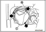
5. Remove the harness clamp (A) from rear housing (1).
6. Remove rear housing and O-ring.
CAUTION:
Remove in the input shaft axial direction because the oil
channel of the rear housing is inserted in the center hole of
the input shaft.
7. Remove 5th main gear assembly, referring to Step 5 to 8 of ŌĆ£Disassembly of TRANSAXLE ASSEMBLYŌĆØ Refer to TM-37, "Disassembly".
INSTALLATION
Note the following, and install in the reverse order of removal.
ŌĆó Shift into 3rd with shifter lever to install the 5th main gear assembly, referring to Step 38 to 41 of ŌĆ£Assembly of TRANSAXLE ASSEMBLY.ŌĆØ Refer to TM-43, "Assembly".
ŌĆó Install O-ring and the rear housing to the transaxle case and tighten the mounting bolts to the specified torque. Refer to TM-33, "Exploded View".
CAUTION:
Never pinch O-ring when installing rear housing.
ŌĆó Refill gear oil. Refer to TM-22, "Refilling".
Inspection
INSPECTION AFTER INSTALLATION
ŌĆó Check the operation of the control linkage. Refer to TM-27, "Inspection".
ŌĆó Check the oil leakage and the oil level. Refer to TM-22, "Inspection".
 Air breather hose
Exploded View
1. Clip
2. Air breather hose
3. 2 way connector
Removal and Installation
REMOVAL
1. Remove clips (1).
: Vehicle front
2. Remove air breather hose from the 2 way connector.
...
 Unit removal and installation
Transaxle assembly
Exploded View
1. Transaxle assembly
: Refer to "INSTALLATION" in
TM-30, "Removal and Installation" for the locations and tightening torque.
Removal and I ...
Other materials:
P0713 transmission fluid temperature sensor A
DTC Logic
DTC CONFIRMATION PROCEDURE
1.PREPARATION BEFORE WORK
If another "DTC CONFIRMATION PROCEDURE" occurs just before, turn ignition
switch OFF and wait for at
least 10 seconds, then perform the next test.
>> GO TO 2.
2.PERFORM DTC CONFIRMATION PROCEDURE
1. Start the ...
B210B starter control relay
DTC Logic
DTC DETECTION LOGIC
NOTE:
If DTC B210B is displayed with DTC U1000, first perform the trouble diagnosis
for DTC U1000. Refer to PCS-
30, "DTC Logic".
DTC CONFIRMATION PROCEDURE
1.PERFORM DTC CONFIRMATION PROCEDURE
1. Press push-button ignition switch under the followin ...
Thermo control amplifier
Removal and Installation
REMOVAL
1. Remove evaporator.
ŌĆó Refer to HA-55, "EVAPORATOR : Removal and Installation". (HR16DE)
ŌĆó Refer to HA-115, "EVAPORATOR : Removal and Installation". (MR16DDT)
2. Remove the thermo control amp. from evaporator.
INSTALLATION
Note the ...
