Nissan Juke Service and Repair Manual : Air breather hose
Exploded View
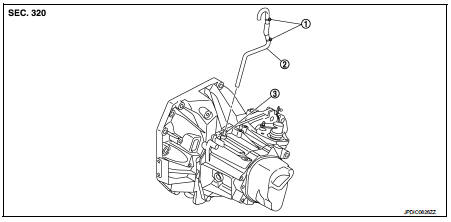
1. Clip
2. Air breather hose
3. 2 way connector
Removal and Installation
REMOVAL
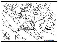
1. Remove clips (1).
 : Vehicle front
2. Remove air breather hose from the 2 way connector.
CAUTION:
When removing air breather hose, be sure to hold 2 way
connector securely.
INSTALLATION
Note the following, and install in the reverse order of removal.
CAUTION:
• Install air breather hose, preventing crush and clogging caused by bending.
• Insert the allowance of air breather hose to the spool of the 2 way connector.
• Install air breather hose to the 2 way connector with the paint mark faced forward of the vehicle.
• Securely engage the clips in the mounting hole.
 Control linkage
Exploded View
1. Bracket
2. Selector cable
3. Shifter lever A
4. Selector lever
5. Cable mounting bracket
6. Tapping bolt
7. Shifter cable
8. Grommet
9. M/T shift selector assembly
1 ...
 5TH main gear assembly
Removal and Installation
REMOVAL
1. Shift the shifter lever to the 3rd gear position.
2. Disconnect the shifter cable and the selector cable from shifter lever A and
selector lever. Refer to TM-2 ...
Other materials:
P0717 input speed sensor A
DTC Logic
DTC DETECTION LOGIC
DTC CONFIRMATION PROCEDURE
CAUTION:
Always drive vehicle at a safe speed.
NOTE:
If “DTC CONFIRMATION PROCEDURE” has been previously performed, always turn
ignition switch
OFF and wait at least 10 seconds before performing the next test.
After the repai ...
P0201, P0202, P0203, P0204 fuel injector
DTC Logic
DTC DETECTION LOGIC
NOTE:
If DTC P0201, P0202, P0203 or P0204 is displayed with DTC P0263, P0266, P0269 or
P0272 first perform
trouble diagnosis for DTC P0263, P0266, P0269 or P0272. Refer to EC-931, "DTC
Logic".
Diagnosis Procedure
1.CHECK FUEL INJECTOR POWER SUPPLY ...
System
Front wiper and washer system (with light & rain sensor)
FRONT WIPER AND WASHER SYSTEM (WITH LIGHT & RAIN SENSOR) : System
Diagram
FRONT WIPER AND WASHER SYSTEM (WITH LIGHT & RAIN SENSOR) : System
Description
OUTLINE
The front wiper is controlled by each function of BCM and IPDM ...
