Nissan Juke Service and Repair Manual : Unit removal and installation
Transaxle assembly
Exploded View
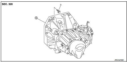
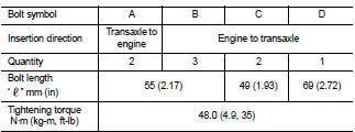
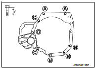
1. Transaxle assembly
 : Refer to "INSTALLATION" in
TM-30, "Removal and Installation" for the locations and tightening torque.
Removal and Installation
CAUTION:
Never reuse CSC (Concentric Slave Cylinder). Because CSC slides back to the
original position every
time when removing transaxle assembly. At this timing, dust on the sliding parts
may damage a seal of
CSC and may cause clutch fluid leakage. Refer to CL-27, "Removal and
Installation".
REMOVAL
1. Disconnect battery cable from negative terminal. Refer to PG-124, "Removal and Installation".
2. Shift the shifter lever to the neutral position.
3. Remove battery. Refer to PG-124, "Removal and Installation".
4. Remove air cleaner case. Refer to EM-161, "Removal and Installation".
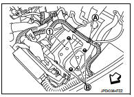
5. Remove bracket (1), as per the following procedure.
 : Vehicle front
a. Disconnect clips (A) from bracket.
b. Remove bolts (B) from bracket.
c. Remove bracket.
6. Remove air breather hose. Refer to TM-28, "Removal and Installation".
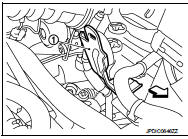
7. Remove bracket (1).
: Vehicle front
8. Disconnect selector cable and shifter cable from transaxle assembly. Refer to TM-25, "Removal and Installation".
9. Remove crankshaft position sensor. Refer to EM-228, "Disassembly and Assembly".
10. Remove clutch tube from CSC (Concentric Slave Cylinder) and then temporarily secure it to a position where it will not inhibit work. Refer to CL-25, "Removal and Installation".
CAUTION:
• Keep painted surface on the body or other parts free of clutch fluid. If it
spills, wipe up immediately
and wash the affected area with water.
• Never depress clutch pedal during removal procedure.
11. Remove fender protector LH. Refer to EXT-22, "Removal and Installation".
12. Disconnect ground cable.
13. Disconnect position switch connector. Refer to TM-24, "Removal and Installation".
14. Remove the harness clamp from rear housing.
15. Remove the engine harness clamp and then temporarily secure it to a position where it will not inhibit work.
16. Remove starter motor. Refer to STR-22, "HR16DE : Removal and Installation".
17. Remove front drive shafts. Refer to FAX-53, "Removal and Installation".
NOTE
:
Insert a suitable plug into differential side oil seal after removing front
drive shaft.
18. Set a suitable jack to transaxle assembly and then set a suitable jack to engine assembly.
CAUTION:
When setting a suitable jack, be careful so that it does not contact with the
switch.
19. Remove engine mounting frame support (LH) (TBD) mounting bolts, as per the following procedure.
a. Remove bolt (A).
: Vehicle front
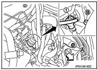
b. Release clutch damper (1) from bracket. Refer to CL-25, "Removal and Installation".
c. Remove bolt (B).
d. Remove engine mounting frame support (LH) mounting bolts from vehicle. Refer to EM-215, "Removal and Installation".
20. Remove rear engine mounting bracket and rear torque rod. Refer to EM-215, "Removal and Installation".
21. Remove transaxle assembly mounting bolts.
22. Remove transaxle assembly from the engine.
CAUTION:
• Fix transaxle assembly to a suitable jack.
• The transaxle assembly must not interfere with the wire harnesses and clutch tube.
23. Remove engine mounting bracket (LH) (TBD) and engine mounting frame support (LH) (TBD) from transaxle assembly. Refer to EM-215, "Removal and Installation".
24. Remove CSC. Refer to CL-27, "Removal and Installation".
INSTALLATION
Note the following, and install in the reverse order of removal.
CAUTION:
• Fix transaxle assembly to a suitable jack.
• The transaxle assembly must not interfere with the wire harnesses and clutch tube.
• When installing transaxle assembly, never bring input shaft into contact with clutch cover.
• Tapping work for tapping bolts is not applied to new clutch housing. Do not perform tapping by other than screwing tapping bolts because tapping is formed by screwing tapping bolts into clutch housing.
• Tighten transaxle assembly mounting bolts to the specified torque.
The figure is the view from the engine.
Inspection
INSPECTION AFTER INSTALLATION
• Check the operation of the control linkage. Refer to TM-27, "Inspection".
• Check the oil leakage and the oil level. Refer to TM-22, "Inspection".
 5TH main gear assembly
Removal and Installation
REMOVAL
1. Shift the shifter lever to the 3rd gear position.
2. Disconnect the shifter cable and the selector cable from shifter lever A and
selector lever. Refer to TM-2 ...

Other materials:
Additional service when replacing TCM
Description
Always perform the following items when the TCM is replaced.
CHECK LOADING OF CALIBRATION DATA
• The TCM acquires calibration data (individual characteristic value) of each
solenoid that is stored in the
ROM assembly (in the control valve). This enables the TCM to perform accur ...
Oil pump
Exploded View
1. Oil pump drive chain
2. Crankshaft sprocket
3. Oil pump assembly
Removal and Installation
REMOVAL
1. Disconnect the battery cable from the negative terminal.
2. Remove engine under cover.
3. Remove front wheel RH. Refer to WT-7, "Exploded View".
4. Remove fen ...
Both side headlamps (HI) are not turned on
Description
Both side headlamps (HI) are not turned ON when setting to the lighting
switch HI or PASS.
Diagnosis Procedure
1.COMBINATION SWITCH INSPECTION
Check the combination switch. Refer to BCS-92, "Symptom Table".
Is the inspection result normal?
YES >> GO TO 2.
NO ...
