Nissan Juke Service and Repair Manual : Final drive
Exploded View
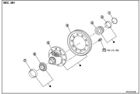
1. Shim
2. Differential side bearing outer race
(transaxle case side)
3. Differential side bearing inner race
(transaxle case side)
4. Final gear
5. Differential case
6. Differential side bearing inner race
(clutch housing side)
7. Differential side bearing outer race
(clutch housing side)
 : Replace the parts as a set.
 : N·m (kg-m, ft-lb)
Disassembly
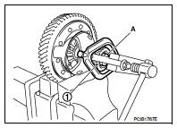
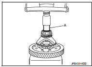
1. Remove differential side bearing inner race (clutch housing side) (1), as per the following procedure.
a. Set a puller [Commercial service tool] to differential side bearing inner race (clutch housing side).
b. Remove differential side bearing inner race (clutch housing side), using the drift (A) [SST: ST33061000].
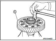
2. Remove final gear mounting bolts, and then remove final gear (1).
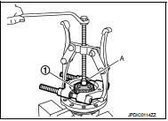
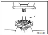
3. Remove differential side bearing inner race (transaxle case side) (1), as per the following procedure.
a. Set a puller [Commercial service tool] to differential side bearing inner race (transaxle case side).
b. Remove differential side bearing inner race (transaxle case side), using a drift (A) [Commercial service tool].
Assembly
1. Install final gear, and then tighten final gear mounting bolts to the specified torque.
CAUTION:
Replace final gear and differential case as a set.
2. Install differential side bearing inner race (clutch housing side), using a drift (A) [Commercial service tool].
CAUTION:
Replace differential side bearing inner race (clutch housing
side) and differential side bearing outer race (clutch housing
side) as a set.
3. Install differential side bearing inner race (transaxle case side), using a drift (A) [Commercial service tool].
CAUTION:
Replace differential side bearing inner race (transaxle case
side) and differential side bearing outer race (transaxle
case side) as a set.
Inspection
INSPECTION AFTER DISASSEMBLY
Gear and Case
Check final gear and differential case. Replace if necessary.
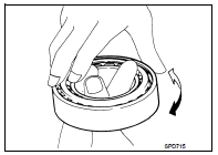
Bearing
Check bearing for damage and unsmooth rotation. Replace if necessary.
 Reverse idler shaft and gear
Exploded View
1. Reverse output gear
2. Snap ring
3. Reverse baulk ring
4. Return spring
5. Needle bearing
6. Seal washer
7. Reverse idler shaft
8. Spacer
9. Reverse input gear
10. L ...
 Service data and specifications (SDS)
General Specifications
...
Other materials:
System
CVT control system : System Diagram
CVT control system : System Description
INPUT/OUTPUT SIGNAL TABLE
*: With Nissan Dynamic Control System
SYSTEM DESCRIPTION
• CVT detects the vehicle driving status from switches, sensors and signals,
and controls the vehicle so that
the optimum shift ...
System
ENGINE CONTROL SYSTEM : System Diagram
1. Priming pump
2. Fuel filter
3. High pressure supply pump
4. High pressure supply pump (internal
transfer pump)
5. High pressure supply pump (volumetric
control valve)
6. High pressure supply pump (high
pressure pump)
7. High pressure supply pum ...
Telematic Control Unit Gen2K
A. INTRODUCTION
The Telematic Control Unit Gen2K, a vital component integrated into your Nissan Leaf, utilizes a sophisticated software architecture comprised of the following elements:
1. Proprietary software developed by, or specifically for, Ficosa International, S.A. ("Ficosa").
2 ...
