
Nissan Juke Service and Repair Manual : Clutch piping
Exploded View
RS5F92R
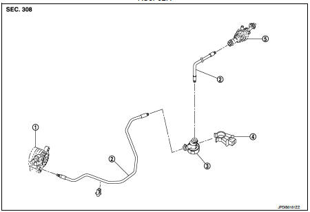
1. CSC (Concentric Slave Cylinder)
2. Clutch tube
3. Clutch damper
4. Bracket
5. Master cylinder
RS6F94R
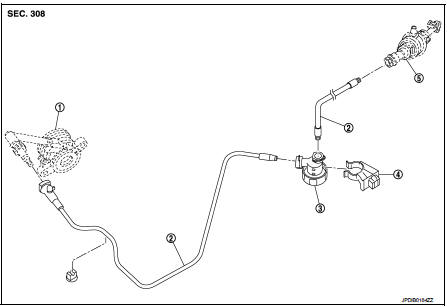
1. CSC (Concentric Slave Cylinder)
2. Clutch tube
3. Clutch damper
4. Bracket
5. Master cylinder
Hydraulic Layout
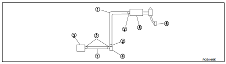
1. Clutch tube
2. Lock pin
3. CSC (Concentric Slave Cylinder)
4. Clutch damper
5. Master cylinder
6. Clutch pedal
Removal and Installation
CAUTION:
Keep painted surface on the body or other parts free of clutch fluid. If it
spills, wipe up immediately
and wash the affected area with water.
REMOVAL
Note the following, and refer to CL-24, "Exploded View" for removal procedure.
• Drain clutch fluid. Refer to CL-10, "RS5F92R : Draining" (RS5F92R) or CL-13, "RS6F94R : Draining" (RS6F94R).
• Press the lock pin into the bleeding connector of the CSC, and then remove clutch tube from CSC.
• Pull the lock pins from the connectors of the clutch damper until the pins stop, and then remove clutch tubes from clutch damper.
• Pull the lock pin from the connector of the clutch master cylinder until the pin stop, and then remove clutch tube from clutch master cylinder.
INSTALLATION
Note the following, and refer to CL-24, "Exploded View" for installation procedure.
CAUTION:
Never damage clutch tube.
• Insert each clutch tube into the CSC bleeding connector, the clutch damper connector, and the clutch master cylinder connector until it contacts the end of each connector.
• Install each lock pin into the clutch damper connector and the clutch master cylinder connector until it contacts the end of each connector.
Inspection and Adjustment
INSPECTION AFTER REMOVAL
• Check the clutch tube for cracks and damage. If the clutch tube has cracks or damage, replace it with a new one.
• Check the O-ring of the clutch tube for cracks and damage. If the O-ring of the clutch tube has cracks or damage, replace clutch tube with a new one.
• Check the clutch damper for cracks and damage. If the clutch damper has cracks or damage, replace it with a new one.
INSPECTION AFTER INSTALLATION
• Check the fluid leakage and the fluid level. Refer to CL-10, "RS5F92R : Inspection" (RS5F92R) or CL-13, "RS6F94R : Inspection" (RS6F94R).
• Check the clutch pedal height, clutch pedal height at clutch disengagement, and clutch pedal play. Refer to CL-7, "Inspection and Adjustment".
ADJUSTMENT AFTER INSTALLATION
Perform the air bleeding. Refer to CL-12, "RS5F92R : Air Bleeding" (RS5F92R) or CL-15, "RS6F94R : Air Bleeding" (RS6F94R).
 Clutch master cylinder
LHD : Exploded View
1. Reservoir hose
2. Reservoir tank
3. Master cylinder
LHD : Removal and Installation
REMOVAL
CAUTION:
• Keep painted surface on the body or other parts free of clutch ...

Other materials:
Component parts
INTERIOR LIGHTING SYSTEM
INTERIOR LIGHTING SYSTEM : Component Parts Location
1. IPDM E/R
Refer to PCS-5, "Component Parts
Location"
2. BCM
Refer to BCS-6, "BODY CONTROL
SYSTEM : Component Parts Location"
3. Door lock and unlock switch
4. Front door request switch (driv ...
Center console assembly
Exploded View
CVT models
1. Console indicator finisher
2. Instrument lower cover RH
3. Center console assembly
4. Instrument lower cover LH
5. Instrument stay
6. CVT shift selector assembly
7. Console rear bracket
8. Console rear finisher
9. Seat heated switch
10. Console switch f ...
P0132 A/F sensor 1
DTC Logic
DTC DETECTION LOGIC
To judge the malfunction, the diagnosis checks that the A/F signal computed
by ECM from the A/F sensor 1
signal is not inordinately high.
DTC CONFIRMATION PROCEDURE
1.PRECONDITIONING
If DTC Confirmation Procedure has been previously conducted, always turn
ig ...
