Nissan Juke Service and Repair Manual : Engine stand setting
NOTE
:
Explained here is how to disassemble with engine stand supporting transaxle
surface. When using different
type of engine stand, note with difference in steps and etc.
1. Remove the engine and the transaxle assembly from the vehicle, and separate the transaxle from the engine. Refer to EM-215, "Exploded View".
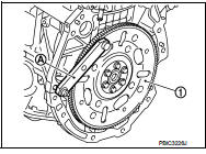
2. Install engine to engine stand with the following procedure: a. Remove flywheel or drive plate.
• Secure flywheel (1) with a stopper plate [SST: KV11105210] (A), and remove mounting bolts (M/T models).
![• Secure driveplate (1) with a stopper plate [SST: KV11105210]](images/books/335/5/index.127.jpg)
• Secure driveplate (1) with a stopper plate [SST: KV11105210] (A), and remove mounting bolts (CVT models).
CAUTION:
• Never disassemble them.
• Never place them with signal plate facing down.
• When handling signal plate, take care not to damage or scratch them.
• Handle signal plate in a manner that prevents them from becoming magnetized.
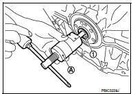
b. Remove pilot converter (1) from the rear end of the crankshaft.
Use a pilot bush puller [SST: ST16610000] (A), if necessary.
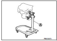
c. Lift the engine with a hoist to install it onto widely use engine stand.
CAUTION
:
• Use the engine stand that has a load capacity [approximately 150 kg (331
lb) or more] large
enough for supporting the engine weight.
• If the load capacity of stand is not adequate, remove the following parts beforehand to reduce the potential risk of overturning stand.
- Intake manifold: Refer to EM-163, "Exploded View".
- Exhaust manifold: Refer to EM-166, "Removal and Installation".
- Rocker cover: Refer to EM-178, "Exploded View".
NOTE
:
The figure shows an example of widely used engine stand (A)
that can support mating surface of transaxle with flywheel
removed.
CAUTION:
Before removing the hanging chains, check the engine
stand is stable and there is no risk of overturning.
3. Drain engine oil. Refer to LU-26, "Draining".
CAUTION:
Be sure to clean drain plug and install with new drain plug washer.
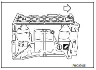
4. Drain engine coolant by removing water drain plug (1) from inside of the engine.
 : Engine front
Tightening torque : Refer to EM-227, "Exploded View".
Use Genuine Liquid Gasket or equivalent.

 Engine unit
Disassembly
1. Remove intake manifold. Refer to EM-163, "Exploded View".
2. Remove exhaust manifold. Refer to EM-166, "Exploded View".
3. Remove oil pan (lower). Refer to EM-16 ...
Other materials:
P0001 fuel pump
DTC Logic
DTC DETECTION LOGIC
NOTE:
If DTC P0001 is displayed with DTC P0560 or P0657, first perform trouble
diagnosis for DTC P0560 or P0657.
Refer to EC-963, "DTC Logic" (DTC P0560) or EC-976, "DTC Logic" (DTC P0657).
Diagnosis Procedure
1.CHECK HIGH PRESSURE SUPPLY ...
Combination switch output circuit
Diagnosis Procedure
1.CHECK OUTPUT 1 - 5 CIRCUIT FOR OPEN
1. Turn ignition switch OFF.
2. Disconnect BCM and combination switch connectors.
3. Check continuity between BCM harness connector and combination switch harness
connector.
Does continuity exist?
YES >> GO TO 2.
NO >> ...
P0197, P0198 EOT sensor
DTC Logic
DTC DETECTION LOGIC
DTC CONFIRMATION PROCEDURE
1.PRECONDITIONING
If DTC Confirmation Procedure has been previously conducted, always perform
the following procedure
before conducting the next test.
1. Turn ignition switch OFF and wait at least 10 seconds.
2. Turn ignition swit ...
