Nissan Juke Service and Repair Manual : B2555 stop lamp
DTC Logic
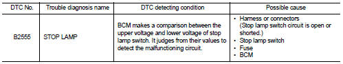
DTC DETECTION LOGIC
DTC CONFIRMATION PROCEDURE
1.PERFORM DTC CONFIRMATION PROCEDURE
1. Depress the brake pedal and wait 1 second or more.
2. Check DTC in тАЬSelf Diagnostic ResultтАЭ mode of тАЬBCMтАЭ using CONSULT-III.
Is DTC detected? YES >> Go to SEC-73, "Diagnosis Procedure".
NO >> INSPECTION END
Diagnosis Procedure
1.CHECK STOP LAMP SWITCH INPUT SIGNAL 1
1. Turn ignition switch OFF.
2. Disconnect BCM connector.
3. Check voltage between BCM harness connector and ground.
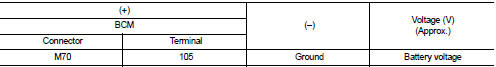
Is the inspection normal? YES >> GO TO 2.
NO-1 >> Check 10 A fuse [No. 38, located in the fuse block (J/B)].
NO-2 >> Check harness for open or short between BCM and fuse.
2.CHECK STOP LAMP SWITCH POWER SUPPLY CIRCUIT
1. Disconnect stop lamp switch connector.
2. Check voltage between stop lamp switch harness connector and ground.
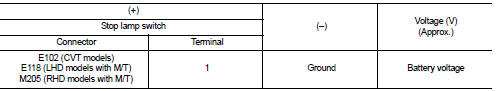
Is the inspection result normal? YES >> GO TO 3.
NO >> Check harness for open or short between stop lamp switch and fuse.
3.CHECK STOP LAMP SWITCH INPUT SIGNAL 2
1. Connect stop lamp switch connector.
2. Check voltage between BCM harness connector and ground.
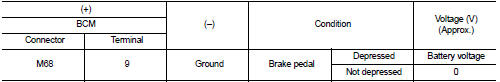
Is the inspecting result normal? YES >> GO TO 4.
NO >> GO TO 5.
4.REPLACE BCM
1. Replace BCM. Refer to BCS-93, "Removal and Installation".
2. Perform initialization of BCM and registration of all Intelligent Keys using CONSULT-III.
For initialization and registration procedures, refer to CONSULT-III Operation Manual NATS-IVIS/NVIS.
>> INSPECTION END
5.CHECK STOP LAMP SWITCH CIRCUIT
1. Disconnect stop lamp switch connector.
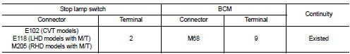
2. Check continuity between stop lamp switch harness connector and BCM harness connector.
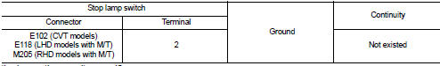
3. Check continuity between stop lamp switch harness connector and ground.
Is the inspection result normal? YES >> GO TO 6.
NO >> Repair or replace harness.
6.CHECK STOP LAMP SWITCH
Refer to SEC-74, "Component Inspection".
Is the inspection result normal? YES >> GO TO 7.
NO >> Replace stop lamp switch. Refer to BR-21, "Removal and Installation" (LHD) or BR-89, "Removal and Installation" (RHD).
7.CHECK INTERMITTENT INCIDENT
Refer to GI-42, "Intermittent Incident".
>> INSPECTION END
Component Inspection
1.CHECK STOP LAMP SWITCH
1. Turn ignition switch OFF.
2. Disconnect stop lamp switch connector.
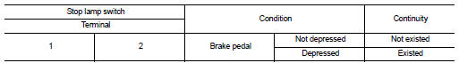
3. Check continuity between stop lamp switch terminals.
Is the inspection result normal? YES >> INSPECTION END
NO >> Replace stop lamp switch. Refer to BR-21, "Removal and Installation" (LHD) or BR-89, "Removal and Installation" (RHD).
 B2014 chain of STRG-IMMU
DTC Logic
DTC DETECTION LOGIC
DTC CONFIRMATION PROCEDURE
1.PERFORM DTC CONFIRMATION PROCEDURE
1. Lock steering.
NOTE:
3. Press the push-button ignition switch.
4. Check DTC in тАЬSelf Dia ...
 B2556 Push-button ignition switch
DTC Logic
DTC DETECTION LOGIC
DTC CONFIRMATION PROCEDURE
1.PERFORM DTC CONFIRMATION PROCEDURE
1. Press push-button ignition switch under the following condition.
- Brake pedal: Not depressed
2 ...
Other materials:
NISSAN Intelligent Key Operation
This hands-free proximity system allows you to completely secure or access your vehicle cabin without ever needing to physically retrieve the Intelligent Key transmitter from your pocket, briefcase, or handbag.
As long as you are personally carrying the registere ...
How to enable/disable the RCTA system
Follow these steps to customize or toggle the RCTA system settings:
1. Press the button repeatedly until "Settings" appears on the vehicle information display.
Use the button to navigate to "Driver Assistance," then press the OK button to enter the s ...
Precaution
Precaution for Supplemental Restraint System (SRS) "AIR BAG" and "SEAT
BELT
PRE-TENSIONER"
The Supplemental Restraint System such as тАЬAIR BAGтАЭ and тАЬSEAT BELT PRE-TENSIONERтАЭ,
used along
with a front seat belt, helps to reduce the risk or severity of injury to the
...
