Nissan Juke Service and Repair Manual : B2014 chain of STRG-IMMU
DTC Logic
DTC DETECTION LOGIC
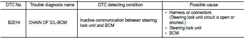
DTC CONFIRMATION PROCEDURE
1.PERFORM DTC CONFIRMATION PROCEDURE
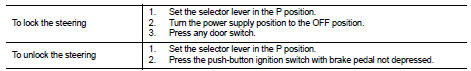
1. Lock steering.
NOTE
:
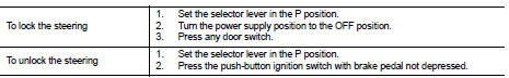
3. Press the push-button ignition switch.
4. Check DTC in “Self Diagnostic Result” mode of “BCM” using CONSULT-III.
Is DTC detected? YES >> Go to SEC-70, "Diagnosis Procedure".
NO >> INSPECTION END
Diagnosis Procedure
1.CHECK STEERING LOCK UNIT POWER SUPPLY
1. Turn ignition switch OFF.
2. Disconnect steering lock unit connector.
3. Check voltage between steering lock unit harness connector and ground.
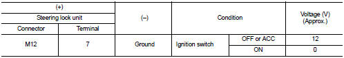
Is the inspection result normal? YES >> GO TO 3.
NO >> GO TO 2.
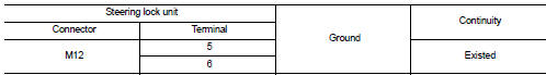
2.CHECK STEERING LOCK UNIT POWER SUPPLY CIRCUIT
1. Disconnect BCM connector.
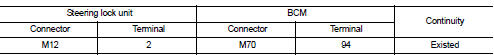
2. Check continuity between steering lock unit harness connector and BCM harness connector.
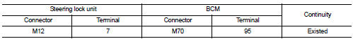
3. Check continuity between steering lock unit harness connector and ground.
Is the inspection result normal? YES >> GO TO 7.
NO >> Repair or replace harness.
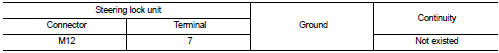
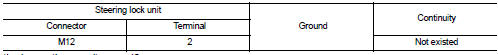
3.CHECK STEERING LOCK UNIT GROUND CIRCUIT
Check continuity between steering lock unit and ground.
Is the inspection result normal? YES >> GO TO 4.
NO >> Repair or replace harness.
4.CHECK STEERING LOCK UNIT COMMUNICATION SIGNAL
1. Connect steering lock unit connector and BCM connector.
2. Read voltage signal between steering lock unit harness connector and ground.
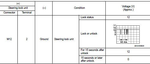
NOTE:
Is the inspection result normal? YES >> GO TO 5.
NO >> GO TO 6.
5.REPLACE STEERING LOCK UNIT
1. Replace steering lock unit.
2. Perform the service procedure for steering lock unit replacement. Refer to CONSULT-III Operation Manual NATS-IVIS/NVIS.
>> INSPECTION END
6.CHECK STEERING LOCK UNIT COMMUNICATION CIRCUIT
1. Disconnect steering lock unit and BCM connector.
2. Check continuity between steering lock unit harness connector and BCM harness connector.
3. Check continuity between steering lock unit harness connector and ground.
Is the inspection result normal? YES >> GO TO 7.
NO >> Repair or replace harness.
7.REPLACE BCM
1. Replace BCM. Refer to BCS-93, "Removal and Installation".
2. Perform initialization of BCM and registration of all Intelligent Keys using CONSULT-III.
For initialization and registration procedures, refer to CONSULT-III Operation Manual NATS-IVIS/NVIS.
>> INSPECTION END
 B2013 steering lock unit
DTC Logic
DTC DETECTION LOGIC
DTC CONFIRMATION PROCEDURE
1.PERFORM DTC CONFIRMATION PROCEDURE
1. Lock the steering.
NOTE:
3. Press the push-button ignition switch.
4. Check DTC in “Self ...
 B2555 stop lamp
DTC Logic
DTC DETECTION LOGIC
DTC CONFIRMATION PROCEDURE
1.PERFORM DTC CONFIRMATION PROCEDURE
1. Depress the brake pedal and wait 1 second or more.
2. Check DTC in “Self Diagnostic Result” ...
Other materials:
Commercial Service Tools
HFC-134a (R-134a) Service Tool and Equipment
• Never mix HFC-134a (R-134a) refrigerant and/or its specified lubricant with
CFC-12 (R-12) refrigerant and/
or its lubricant.
• Separate and non-interchangeable service equipment must be used for handling
each type of refrigerant/
lubricant.
...
Diagnosis and repair work flow
Work Flow
OVERALL SEQUENCE
Reference 1··· Refer to AV-33, "MODELS WITH USB CONNECTION FUNCTION : Symptom
Table" (with USB
connection function) or AV-35, "MODELS WITHOUT USB CONNECTION FUNCTION : Symptom
Table" (without
USB connection function).
DETAILED FLOW
1.CH ...
P1553 battery current sensor
DTC Logic
DTC DETECTION LOGIC
DTC CONFIRMATION PROCEDURE
1.PRECONDITIONING
If DTC Confirmation Procedure has been previously conducted, always perform
the following before conducting
the next test.
1. Turn ignition switch OFF and wait at least 10 seconds.
2. Turn ignition switch ON.
3. ...
