Nissan Juke Service and Repair Manual : System
Warning chime system
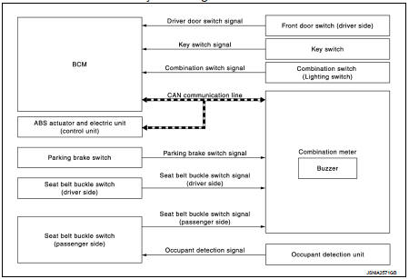
WARNING CHIME SYSTEM : System Diagram
WARNING CHIME SYSTEM : System Description
COMBINATION METER
The combination meter sounds the alarm buzzer installed in the combination meter when receiving the buzzer output signal transmitted from each unit.
BCM
BCM receives signals from various units and transmits a buzzer output signal to
the combination meter via
CAN communication if it judges that the warning buzzer should be activated.
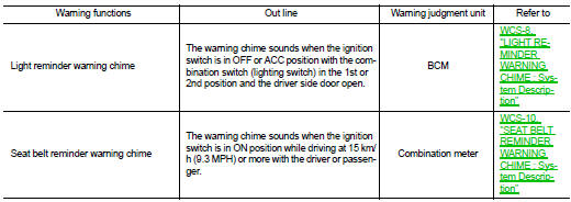
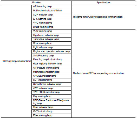
WARNING CHIME FUNCTION LIST
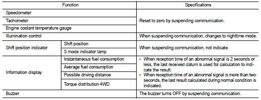
WARNING CHIME SYSTEM : Fail-Safe
FAIL-SAFE
The combination meter activates the fail-safe control if CAN communication with each unit is malfunctioning.
Light reminder warning chime
LIGHT REMINDER WARNING CHIME : System Dia
LIGHT REMINDER WARNING CHIME : System Description
WARNING CHIME OPERATION CONDITIONS
If all of the following conditions are fulfilled.
WARNING CHIME CANCEL CONDITIONS
Warning is canceled if any of the following conditions is fulfilled.
SIGNAL PATH
1. BCM requires warning chime output to combination meter when it judges light reminder warning chime is necessary from signals below.
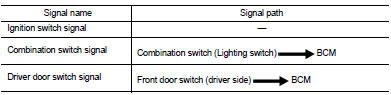
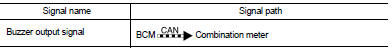
2. Combination meter sounds integrated buzzer, following the warning chime output requirement (below signal) from BCM.
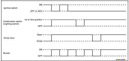
TIMING CHART
Seat belt reminder warning chime
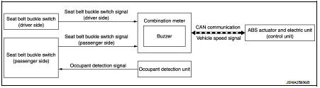
SEAT BELT REMINDER WARNING CHIME : System Diagram
SEAT BELT REMINDER WARNING CHIME : System Description
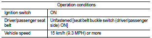
WARNING OPERATION CONDITIONS
If all of the following conditions are fulfilled.
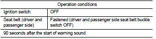
WARNING CANCEL CONDITIONS
Warning is canceled if any of the following conditions is fulfilled.
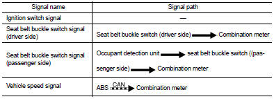
SIGNAL PATH
Combination meter sounds integrated buzzer when it judges that seat belt warning chime is necessary from signals below.
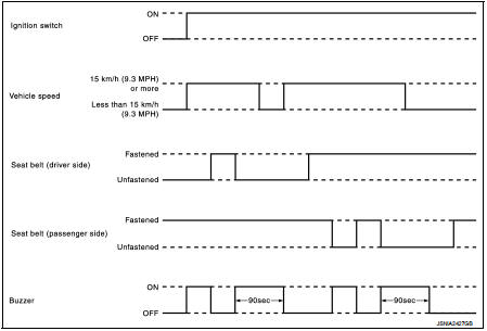
TIMING CHART
SOUND SPECIFICATION
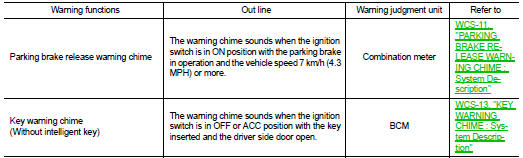
Parking brake release warning chime
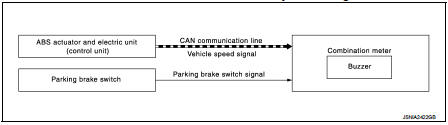
PARKING BRAKE RELEASE WARNING CHIME : System Diagram
PARKING BRAKE RELEASE WARNING CHIME : System Description
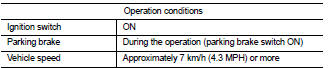
WARNING OPERATION CONDITIONS
If all of the following conditions are fulfilled.
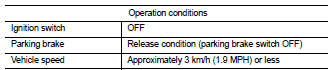
WARNING CANCEL CONDITIONS
Warning is canceled if any of the following conditions are fulfilled.
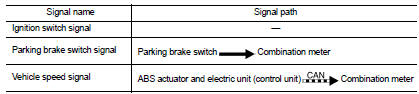
SIGNAL PATH
Combination meter sounds integrated buzzer when it judges that parking brake release warning chime is necessary from signals below.
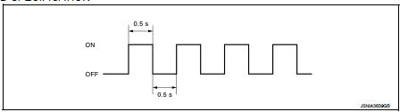
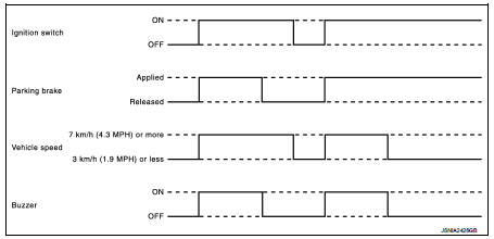
TIMING CHART
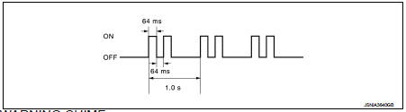
SOUND SPECIFICATION
Key warning chime
KEY WARNING CHIME : System Diagram
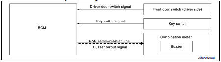
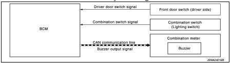
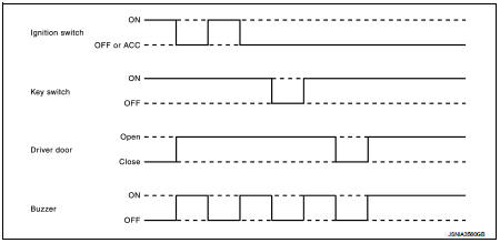
KEY WARNING CHIME : System Description
DESCRIPTION
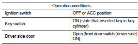
The warning chime sounds when the ignition switch is in OFF or ACC position with the key inserted and the driver side door open.
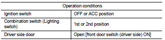
WARNING OPERATION CONDITIONS
The BCM transmits the buzzer output signal to combination meter with CAN communication line when all of the following operation conditions are met. When combination meter receives buzzer output signal, it sounds the buzzer
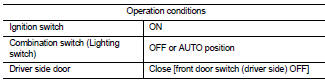
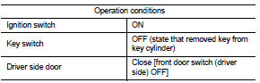
WARNING CANCEL CONDITIONS
Warning is canceled if any of the following conditions is fulfilled.
SIGNAL PATH
1. BCM requires warning chime output to combination meter when it judges key warning chime is necessary from signals below.
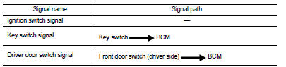
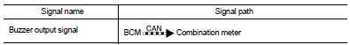
2. Combination meter sounds integrated buzzer, following the warning chime output requirement (below signal) from BCM.
TIMING CHART
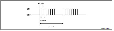
SOUND SPECIFICATION
 Component parts
Component Parts Location
1. Parking brake switch
2. Seat belt buckle switch (passenger
side)
3. Occupant detection unit
(Under the passenger seat cushion
pad)
4. ABS actuator and electric un ...
 Diagnosis system (combination meter)
Consult-III Function
CONSULT-III APPLICATION ITEMS
CONSULT-III can perform the following diagnosis modes via CAN communication
and the combination meter.
SELF DIAG RESULT
Refer to MWI-36, &quo ...
Other materials:
C1120, C1122, C1124, C1126 ABS in valve system
DTC Logic
DTC DETECTION LOGIC
DTC CONFIRMATION PROCEDURE
1.PRECONDITIONING
If “DTC CONFIRMATION PROCEDURE” has been previously conducted, always turn
ignition switch OFF and
wait at least 10 seconds before conducting the next test.
>> GO TO 2.
2.CHECK DTC DETECTION
With CON ...
Exhaust valve timing control
Exhaust valve timing control : System Diagram
Exhaust valve timing control: System Description
INPUT/OUTPUT SIGNAL CHART
SYSTEM DESCRIPTION
This mechanism hydraulically controls cam phases continuously with the fixed
operating angle of the exhaust
valve.
The ECM receives signals such ...
Component parts
Component Parts Location
LHD
2WD
1. ECM
Refer to EC-25, "ENGINE CONTROL
SYSTEM :
Component Parts Location"
(MR16DDT), EC-455, "ENGINE
CONTROL SYSTEM :
Component Parts Location"
(HR16DE), EC-813, "Component
Parts Location" (K9K).
2. TCM*1
Refer to TM-314, ...
