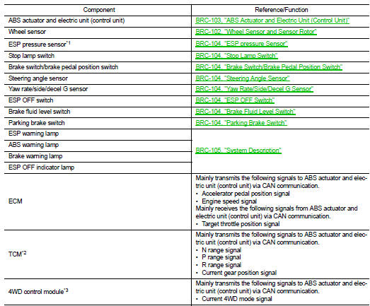
Nissan Juke Service and Repair Manual : Component parts
Component Parts Location
LHD
2WD
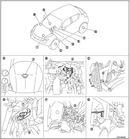
1. ECM Refer to EC-25, "ENGINE CONTROL SYSTEM : Component Parts Location" (MR16DDT), EC-455, "ENGINE CONTROL SYSTEM : Component Parts Location" (HR16DE), EC-813, "Component Parts Location" (K9K).
2. TCM*1 Refer to TM-314, "CVT CONTROL SYSTEM : Component Parts Location".
3. Yaw rate/side/decel G sensor
4. ABS actuator and electric unit (control
unit)
5. ESP pressure sensor*2
6. Front wheel sensor
7. Stop lamp switch
8. Brake switch/brake pedal position
switch
9. Steering angle sensor
10. Rear wheel sensor
A. Under floor carpet (front seat right
side)
B. Inside engine room
C. Steering knuckle
D. Brake pedal
E. ABS warning lamp, brake warning
lamp, ESP warning lamp, ESP OFF
indicator lamp (in combination
meter)
F. Back of spiral cable assembly
G. Rear wheel hub and bearing assembly
*1: Models with CVT
*2: Models with HR16DE and MR16DDT
4WD
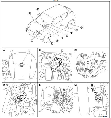
1. ECM Refer to EC-25, "ENGINE CONTROL SYSTEM : Component Parts Location".
2. TCM Refer to TM-131, "CVT CONTROL SYSTEM : Component Parts Location".
3. 4WD control module Refer to DLN-10, "Component Parts Location".
4. Yaw rate/side/decel G sensor
5. ABS actuator and electric unit (control
unit)
6. ESP pressure sensor
7. Front wheel sensor
8. Stop lamp switch
9. Brake switch/brake pedal position
switch
10. Steering angle sensor
11. Rear wheel sensor
A. Under floor carpet (front seat right
side)
B. Inside engine room
C. Steering knuckle
D. Brake pedal
E. ABS warning lamp, brake warning
lamp, ESP warning lamp, ESP OFF
indicator lamp (in combination
meter)
F. Back of spiral cable assembly
G. Rear axle housing
RHD
2WD
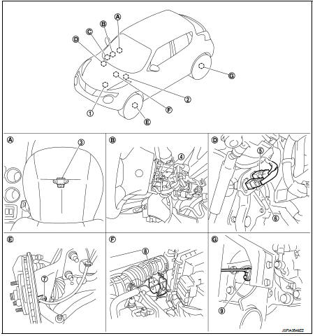
1. ECM Refer to EC-25, "ENGINE CONTROL SYSTEM : Component Parts Location" (MR16DDT), EC-455, "ENGINE CONTROL SYSTEM : Component Parts Location" (HR16DE), EC-813, "Component Parts Location" (K9K).
2. TCM* Refer to TM-314, "CVT CONTROL SYSTEM : Component Parts Location".
3. Yaw rate/side/decel G sensor
4. Steering angle sensor
5. Stop lamp switch
6. Brake switch/brake pedal position
switch
7. Front wheel sensor
8. ABS actuator and electric unit (control
unit)
9. Rear wheel sensor
A. Under floor carpet (front seat right
side)
B. Back of spiral cable assembly
C. ABS warning lamp, brake warning
lamp, ESP warning lamp, ESP OFF
indicator lamp (in combination
meter)
D. Brake pedal E. Steering knuckle
F. Inside engine room
G. Rear wheel hub and bearing assembly
*: Models with CVT
4WD
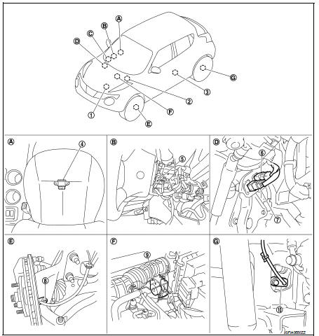
1. ECM Refer to EC-25, "ENGINE CONTROL SYSTEM : Component Parts Location".
2. TCM Refer to TM-131, "CVT CONTROL SYSTEM : Component Parts Location".
3. 4WD control module
Refer to DLN-10, "Component Parts
Location"
4. Yaw rate/side/decel G sensor
5. Steering angle sensor
6. Stop lamp switch
7. Brake switch/brake pedal position
switch
8. Front wheel sensor
9. ABS actuator and electric unit (control
unit)
10. Rear wheel sensor
A. Under floor carpet (front seat right
side)
B. Back of spiral cable assembly
C. ABS warning lamp, brake warning
lamp, ESP warning lamp, ESP OFF
indicator lamp (in combination
meter)
D. Brake pedal E. Steering knuckle
F. Inside engine room
G. Rear axle housing
Component Description
*1: Models with LHD (MR16DDT and HR16DE)
*2: Models with CVT
*3: 4WD models
Wheel Sensor and Sensor Rotor
NOTE
:
• Wheel sensor of front wheel is installed on steering knuckle.
• Sensor rotor of front wheel is integrated in wheel hub and bearing assembly.
• Wheel sensor of rear wheel is installed on wheel hub and bearing assembly.
(2WD)
• Wheel sensor of rear wheel is installed on axle housing. (4WD)
• Sensor rotor of rear wheel is integrated in wheel hub and bearing assembly.
(2WD)
• Sensor rotor of rear wheel is integrated on drive shaft. (4WD)
• Never measure resistance and voltage value using a tester because sensor is
active sensor.
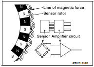
• Downsize and weight reduction is aimed. IC for detection portion and magnet for sensor rotor are adopted.
• Power supply is supplied to detection portion so that magnetic field line is read. Magnetic field that is detected is converted to current signal.
• When sensor rotor rotates, magnetic field changes. Magnetic field change is converted to current signals (rectangular wave) and is transmitted to ABS actuator and electric unit (control unit). Change of magnetic field is proportional to wheel speed.
ABS Actuator and Electric Unit (Control Unit)
Electric unit (control unit) is integrated with actuator and comprehensively controls ESP function, TCS function, ABS function, EBD function and brake limited slip differential (BLSD) function.
ELECTRIC UNIT (CONTROL UNIT)
• Brake fluid pressure, engine and transaxle are controlled according to signals from each sensor.
• If malfunction is detected, the system enters fail-safe mode.
ACTUATOR
The following components are integrated with ABS actuator.
Pump
Returns the brake fluid reserved in reservoir to master cylinder by reducing
pressure.
Motor
Activates the pump according to signals from ABS actuator and electric unit
(control unit).
Motor Relay
Operates the motor ON/OFF according to signals from ABS actuator and electric
unit (control unit).
Actuator Relay (Main Relay) Operates each valve ON/OFF according to signals from ABS actuator and electric unit (control unit).
ABS IN Valve
Switches the fluid pressure line to increase or hold according to signals from
control unit.
NOTE
:
Valve is a solenoid valve.
ABS OUT Valve
Switches the fluid pressure line to increase, hold or decrease according to
signals from control unit.
NOTE
:
Valve is a solenoid valve.
Cut Valve 1, Cut Valve2
Shuts off the ordinary brake line from master cylinder, when ESP function, TCS
function and brake limited slip
differential (BLSD) function are activated.
Suction Valve 1, Suction Valve 2 Supplies the brake fluid from master cylinder to the pump, when ESP function, TCS function and brake limited slip differential (BLSD) function are activated.
Inlet Valve
Brake fluid sucked from the reservoir by the pump does not backflow.
NOTE
:
Valve is a check valve.
Outlet Valve
Brake fluid discharged from the pump does not backflow.
NOTE
:
Valve is a check valve.
Return Check Valve
Returns the brake fluid from brake caliper to master cylinder by bypassing
orifice of each valve when brake is
released.
Reservoir
Temporarily reserves the brake fluid drained from brake caliper, so that
pressure efficiently decreases when
decreasing pressure of brake caliper.
ESP pressure Sensor
Detects the brake fluid pressure and transmits signal to ABS actuator and electric unit (control unit).
Stop Lamp Switch
Detects the operation status of brake pedal and transmits converted electric signal to ABS actuator and electric unit (control unit).
Brake Switch/Brake Pedal Position Switch
Detects the operation status of brake pedal and transmits converted electric signal to ABS actuator and electric unit (control unit).
Steering Angle Sensor
Detects the following information and transmits steering angle signal to ABS actuator and electric unit (control unit) via CAN communication.
• Steering wheel rotation amount • Steering wheel rotation angular velocity • Steering wheel rotation direction
Yaw Rate/Side/Decel G Sensor
Calculates the following information that affects the vehicle, and transmits a signal to ABS actuator and electric unit (control unit) via communication lines.
• Vehicle rotation angular velocity (yaw rate signal) • Vehicle lateral acceleration (side G signal) and longitudinal acceleration (decel G signal)
ESP OFF Switch
• This is an integrated switch with switches for other functions.
• Non-operational status or standby status of the following functions can be selected using ESP OFF switch.
ESP OFF indicator lamp indicates the operation status of function. (ON:
Non-operational status, OFF:
Standby status)
- ESP function
NOTE
:
Brake limited slip differential (BLSD) function control operates.
- TCS function
• ESP OFF indicator lamp turns OFF (standby status) when the engine is started
again after it is stopped once
while ESP OFF indicator lamp is ON (non-operational status).
Brake Fluid Level Switch
Detects the brake fluid level in reservoir tank and transmits converted electric signal from combination meter to ABS actuator and electric unit (control unit) via CAN communication, when brake fluid level is the specified level or less.
Parking Brake Switch
Detects the operation status of parking brake switch and transmits converted electric signal from combination meter to ABS actuator and electric unit (control unit).

 System
System Description
• The system switches fluid pressure of each brake caliper to increase, to
hold or to decrease according to
signals from control unit in ABS actuator and electric unit (contro ...
Other materials:
Headlamp
Exploded View
REMOVAL
1. Headlamp assembly
2. EPT sealer [2.8 mm (0.110 in)]
: Do not reuse
: N·m (kg-m, in-lb)
DISASSEMBLY
1. Back cover
2. Halogen bulb
3. Headlamp housing assembly
4. Retaining spring
5. EPT sealer [2.8 mm (0.110 in)]
: Do not reuse
Removal and Installation
...
Precaution for Supplemental Restraint System (SRS) "AIR BAG" and "SEAT BELT
PRE-TENSIONER"
The Supplemental Restraint System such as “AIR BAG” and “SEAT BELT PRE-TENSIONER”,
used along
with a front seat belt, helps to reduce the risk or severity of injury to the
driver and front passenger for certain
types of collision. Information necessary to service the system safely is
...
P0605 ECM
DTC Logic
DTC DETECTION LOGIC
DTC CONFIRMATION PROCEDURE
1.PRECONDITIONING
If DTC Confirmation Procedure has been previously conducted, always turn
ignition switch OFF and wait at
least 10 seconds before conducting the next test.
>> GO TO 2.
2.PERFORM DTC CONFIRMATION PROCEDURE ...
