Nissan Juke Service and Repair Manual : Diagnosis system (combination meter)
Consult-III Function
CONSULT-III APPLICATION ITEMS
CONSULT-III can perform the following diagnosis modes via CAN communication and the combination meter.
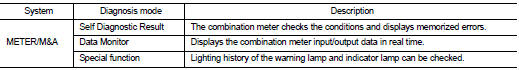
SELF DIAG RESULT
Refer to MWI-36, "DTC Index".
DATA MONITOR
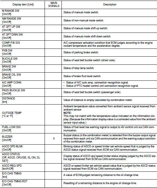
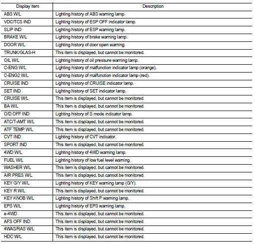
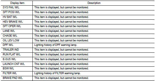
Display Item List
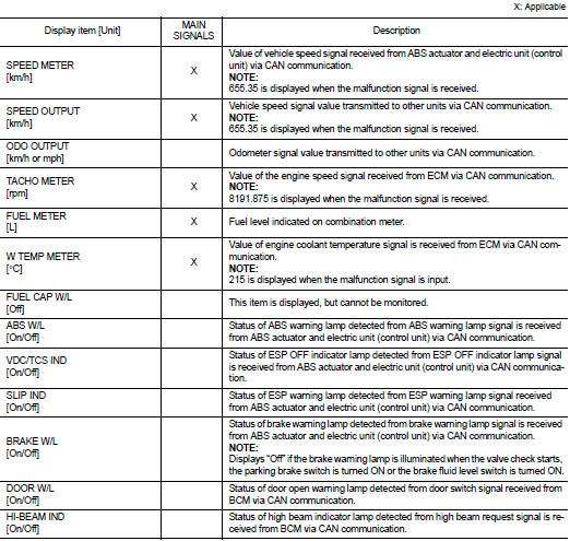
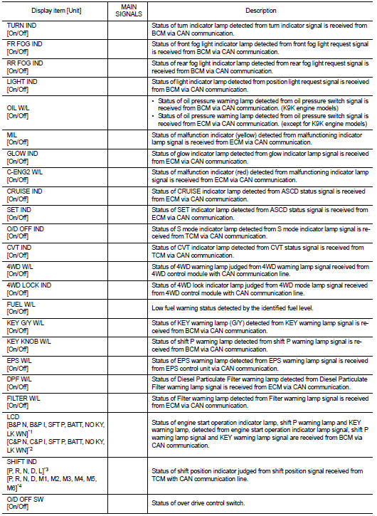
ÔÇó *1: CVT models
ÔÇó *2: M/T models
ÔÇó *3: Without manual mode CVT
ÔÇó *4: With manual mode CVT
NOTE
:
Some items are not available according to vehicle specification.
SPECIAL FUNCTION
Special menu

W/L ON HISTORY
ÔÇó Stores histories when warning/indicator lamp is turned on.
ÔÇó ÔÇťW/L ON HISTORYÔÇŁ indicates the ÔÇťTIMEÔÇŁ when the warning/ indicator lamp is turned on.
ÔÇó The ÔÇťTIMEÔÇŁ above is:
- 0: The condition that the warning/indicator lamp has been turned on 1 or more
times after starting the engine
and waiting for 30 seconds.
- 1 - 39: The number of times the engine was restarted after the 0 condition.
- NO W/L ON HISTORY: Stores NO (0) turning on history of warning/indicator lamp.
NOTE
:
ÔÇó W/L ON HISTORY is not stored for approximately 30 seconds after the engine
starts.
ÔÇó Brake warning lamp does not store any history when the parking brake is applied or the brake fluid level gets low.
Display Item
 System
Warning chime system
WARNING CHIME SYSTEM : System Diagram
WARNING CHIME SYSTEM : System Description
COMBINATION METER
The combination meter sounds the alarm buzzer installed in the combination ...
 Diagnosis system (bcm) (with intelligent key system)
Common item
COMMON ITEM : CONSULT-III Function (BCM - COMMON ITEM)
APPLICATION ITEM
CONSULT-III performs the following functions via CAN communication with BCM.
SYSTEM APPLICATION
BCM can perfo ...
Other materials:
B2614 ACC relay circuit
DTC Logic
DTC DETECTION LOGIC
DTC CONFIRMATION PROCEDURE
1.PERFORM DTC CONFIRMATION PROCEDURE
1. Turn the power supply position to ACC under the following conditions, and
wait for 2 second or more.
CVT models
- Selector lever is in the P or N position
- Do not depress brake pedal
M/T m ...
Inside mirror
Exploded View
Manual anti-dazzling type
1. Windshield glass
2. Mirror base
3. Inside mirror assembly
: Do not reuse
Auto anti-dazzling type
1. Rain sensor bracket
2. Mirror base
3. Rain sensor
4. Inside mirror assembly
: Pawl
: Do not reuse
Removal and Installation
CAUTION:
Ne ...
Back door request switch
Component Function Check
1.CHECK FUNCTION
1. Select ÔÇťINTELLIGENT KEYÔÇŁ of ÔÇťBCMÔÇŁ using CONSULT-III.
2. Select ÔÇťREQ SW-BD/TRÔÇŁ in ÔÇťDATA MONITORÔÇŁ mode.
3. Check that the function operates normally according to the following
conditions.
Is the inspection result normal?
YES >&g ...
