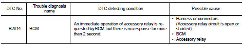
Nissan Juke Service and Repair Manual : B2614 ACC relay circuit
DTC Logic
DTC DETECTION LOGIC
DTC CONFIRMATION PROCEDURE
1.PERFORM DTC CONFIRMATION PROCEDURE
1. Turn the power supply position to ACC under the following conditions, and wait for 2 second or more.
CVT models
- Selector lever is in the P or N position
- Do not depress brake pedal
M/T models
- Do not depress clutch pedal
2. Check “Self-diagnosis result” of BCM with CONSULT-III.
Is DTC detected? YES >> Go to PCS-91, "Diagnosis Procedure".
NO >> INSPECTION END
Diagnosis Procedure
1.CHECK ACCESSORY RELAY POWER SUPPLY-1
1. Turn ignition switch OFF.
2. Disconnect accessory relay.
3. Check voltage between accessory relay harness connector and ground.
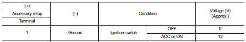
Is the inspection result normal? YES >> GO TO 3.
NO >> GO TO 2.
2.CHECK ACCESSORY RELAY POWER SUPPLY CIRCUIT
1. Turn ignition switch OFF.
2. Disconnect BCM connector.
3. Check continuity between accessory relay harness connector and BCM harness connector.

4. Check continuity between accessory relay harness connector and ground.
Is the inspection result normal? YES >> Replace BCM. Refer to BCS-93, "Removal and Installation".
NO >> Repair or replace harness.
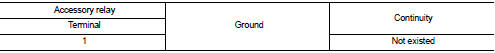
3.CHECK ACCESSORY RELAY GROUND CIRCUIT
1. Turn ignition switch OFF.
2. Check continuity between accessory relay harness connector and ground.

Is the inspection result normal? YES >> GO TO 4.
NO >> Repair accessory relay ground circuit.
4.CHECK ACCESSORY RELAY POWER SUPPLY CIRCUIT-2
1. Turn ignition switch ACC.
2. Check voltage between accessory relay harness connector and ground.
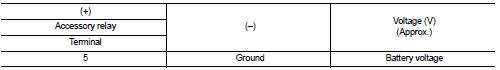
Is the inspection result normal? YES >> GO TO 5.
NO >> Check continuity open or short between accessory relay and battery.
5.CHECK ACCESSORY RELAY
Refer to PCS-92, "Component Inspection".
Is the inspection result normal? YES >> GO TO 6.
NO >> Replace accessory relay.
6.CHECK INTERMITTENT INCIDENT
Refer to GI-42, "Intermittent Incident".
>> INSPECTION END
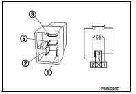
Component Inspection
1.CHECK ACCESSORY RELAY
1. Turn ignition switch OFF.
2. Remove accessory relay.
3. Check the continuity between accessory relay terminals.
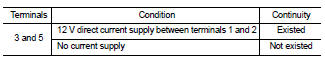
Is the inspection result normal? YES >> INSPECTION END
NO >> Replace accessory relay

 B2615 blower relay circuit
DTC Logic
DTC DETECTION LOGIC
DTC CONFIRMATION PROCEDURE
1.PERFORM DTC CONFIRMATION PROCEDURE
1. Turn ignition switch ON under the following conditions, and wait for 1
second or more.
CVT m ...
Other materials:
Rear bumper
Exploded View
1. Bumper side bracket LH
2. Bumper closing LH
3. Bumper fascia assembly
4. Reflex reflector LH
5. Rear panel lower
6. U nut
7. Bumper fascia lower
8. Reflex reflector RH
9. Bumper stay LH
10. screw grommet
11. Bumper energy absorber
12. Bumper stay RH
13. Bumper ...
Back door
Exploded View
REMOVAL
1. Back door weather-strip
2. Back door stay
3. Back door stay lower bracket
4. Bumper rubber
5. Back door striker
6. Back door panel
7. Back door hinge
8. Hole cover
A : Center mark
B : Seam
: Do not reuse
: Body grea
Back door assembly
BACK DOOR ASSEMBLY ...
Air cleaner filter
Exploded View
1. Hose clamp
2. PCV hose
3. Hose clamp
4. Air cleaner filter
5. Air cleaner filter case
6. Grommet
7. Inlet Air duct (lower)
8. Grommet
9. Inlet Air duct (upper)
10. Bracket
11. Air cleaner case
12. O-ring
13. Mass air flow sensor
14. Air duct
A. To electric ...
