Nissan Juke Service and Repair Manual : Rear bumper
Exploded View
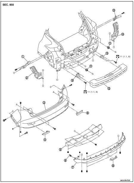
1. Bumper side bracket LH
2. Bumper closing LH
3. Bumper fascia assembly
4. Reflex reflector LH
5. Rear panel lower
6. U nut
7. Bumper fascia lower
8. Reflex reflector RH
9. Bumper stay LH
10. screw grommet
11. Bumper energy absorber
12. Bumper stay RH
13. Bumper closing RH
14. Bumper side bracket RH
 : Pawl
 : Do not reuse
 : N·m (kg-m, ft-lb)
Removal and Installation
CAUTION:
Bumper fascia is made of resin. Never apply strong force to it, and be careful
to prevent contact with
oil.
REMOVAL
1. Fully open back door.
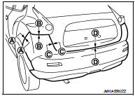
2. Remove bumper fascia mounting screws of rear combination lamp (LH and RH) lower side.
3. Remove rear fillet molding rear side. Refer to EXT-27, "REAR FILLET MOLDING : Removal and Installation".
4. Remove bumper closing.
5. Remove clips of bumper lower side.
6. Remove bumper fascia assembly fixing screws (A) (LH and RH).
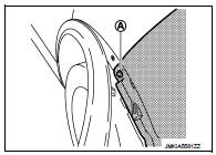
7. Pull bumper fascia side toward the vehicle side to disengage the fitting of bumper side bracket and bumper fascia side as shown by the arrow in the figure.
 : Pawl
CAUTION:
When removing bumper fascia, 2 workers are required so
as to prevent it from dropping.
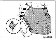
8. Disconnect rear fog lamp harness connector.
9. Remove bumper fascia assembly.
10. Remove the following parts after removing rear bumper fascia.
• Bumper fascia lower
• Bumper finisher
• Reflex reflector (LH and RH).
11. Remove bumper energy absorber.
12. Remove rear panel lower.
13. Remove bumper stay (LH and RH).
14. Remove bumper side bracket fixing screws, and then remove bumper side bracket (LH and RH).
INSTALLATION
Note the following items, and then install in the reverse order of removal.
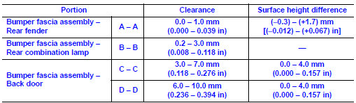
NOTE
:
• The following table shows the specified values for checking normal
installation status.
• Fitting adjustment cannot be performed.
 Front bumper
Exploded View
1. Front side grille RH
2. Front side grille LH
3. Bumper side bracket RH
4. Front center grille
5. Emblem
6. Bumper reinforcement
7. Energy absorber
8. Bumper end rubber ...
 Front grille
Exploded View
1. Bumper fascia assembly
2. Front side grille RH
3. Front center grille
4. Emblem
5. Front side grille LH
: Pawl
Removal and Installation
REMOVAL
CAUTION:
When remove fro ...
Other materials:
P range interlock door lock/unlock function does not operate
Diagnosis Procedure
1.CHECK “AUTOMATIC LOCK/UNLOCK SELECT” SETTING IN “WORK SUPPORT”
1. Select “DOOR LOCK” of “BCM” using CONSULT-III.
2. Select “AUTOMATIC LOCK/UNLOCK SELECT” in “WORK SUPPORT” mode.
3. Check “AUTOMATIC LOCK/UNLOCK SELECT” in “WORK SUPPORT”.
Re ...
Exterior rear
1. Lift gate
— Intelligent Key system
2. Rear window wiper and washer
— Switch operation
— Window washer fluid
3. Rear spoiler
4. High-mounted stop light
5. Antenna
— Satellite radio antenna
6. Rear window defroster
7. Fuel-filler door
— Operation
— Fuel recommend ...
Diagnosis system (bcm) (without intelligent key system)
Common item
COMMON ITEM : CONSULT-III Function (BCM - COMMON ITEM)
APPLICATION ITEM
CONSULT-III performs the following functions via CAN communication with BCM.
SYSTEM APPLICATION
BCM can perform the following functions for each system.
NOTE:
It can perform the diagnosis modes except the ...
