Nissan Juke Service and Repair Manual : Front grille
Exploded View
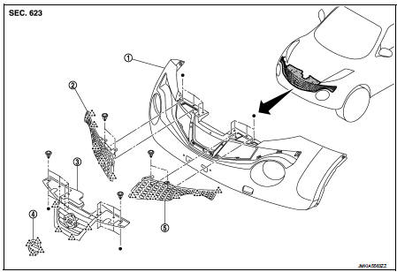
1. Bumper fascia assembly
2. Front side grille RH
3. Front center grille
4. Emblem
5. Front side grille LH
 : Pawl
Removal and Installation
REMOVAL
CAUTION:
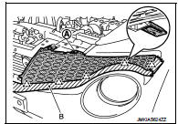
When remove front grilles (1) apply protective tape (A) on the
bumper fascia (2) to protect the painted surface from damage.
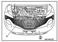
1. Fully open hood assembly.
2. Remove front center grille upper fixing clips (A).
CAUTION:
Apply protective tape (B) around bumper fascia
.
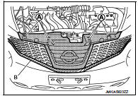
3. Disengage fixing pawls from back side while pulling front center grille to wade vehicle front, and then remove front center grille.
: Pawl
4. Remove front side grille (LH and RH) upper fixing clips (A).
5. Disengage fixing pawls from back side of front side grille (LH and RH).
: Pawl
CAUTION:
Apply protective tape (B) around bumper fascia.
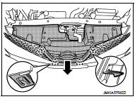
6. Remove front side grille (LH and RH) to ward vehicle front.
7. Remove emblem after removing front grille.
INSTALLATION
Install in the reverse order of removal.
 Rear bumper
Exploded View
1. Bumper side bracket LH
2. Bumper closing LH
3. Bumper fascia assembly
4. Reflex reflector LH
5. Rear panel lower
6. U nut
7. Bumper fascia lower
8. Reflex reflector RH ...
 Cowl top
Exploded View
LHD models
1. Front fender cover RH
2. Cowl top cover seal
3. Blind plug RH
4. Cowl top cover
5. Cowl top cover cap
6. Cowl top extension
7. EPT seal [t: 3.0 mm (0.118 in)] ...
Other materials:
Water hose
Exploded View
1. Hose clamp
2. Water hose A
3. Water hose B
4. Water hose B
5. Water bypass pipe
6. Hose clamp
7. Heater hose
8. Water hose C
A. Water outlet
B. Heater thermostat
C. Oil warmer
D. Heater core
: N·m (kg-m, in-lb)
Removal and Installation
REMOVAL
WARNING:
Nev ...
Exhaust gas (carbon monoxide)
WARNING
• Do not breathe exhaust gases; they contain colorless and odorless carbon
monoxide. Carbon monoxide is dangerous. It can cause unconsciousness or death.
• If you suspect that exhaust fumes are entering the vehicle, drive with all windows
fully open, and have the vehicle inspected ...
Condenser
Exploded View
Refer toINT-34, "Exploded View"
Removal and Installation
REMOVAL
1. Remove the back door lower finisher.
Refer to INT-35, "BACK DOOR LOWER FINISHER : Removal and Installation"
2. Remove bolt (A), and then remove condenser (1) from the vehicle
body.
INSTA ...
