Nissan Juke Service and Repair Manual : Cowl top
Exploded View
LHD models
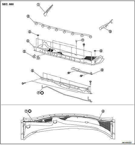
1. Front fender cover RH
2. Cowl top cover seal
3. Blind plug RH
4. Cowl top cover
5. Cowl top cover cap
6. Cowl top extension
7. EPT seal [t: 3.0 mm (0.118 in)]
8. Air intake cover
9. Blind plug LH
10. Front fender cover LH
11. Washer nozzle
 : Clip
 : Pawl
 : Do not reu
Removal and Installation
REMOVAL
1. Fully open hood assembly 2. Remove front wiper arm (LH and RH). Refer to WW-76, "Removal and Installation".
3. Disconnect washer tube joint on cowl top cover RH.
4. Remove front fender cover (LH and RH).
5. Remove cowl top cover fixing clips.
6. Pull forward to release cowl top cover from windshield glass.
CAUTION:
When performing the procedure after removing cowl top
cover, cover the lower end of windshield glass with urethane
etc.
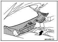
7. Remove cowl top cover.
8. Remove the following parts after removing cowl top cover.
• EPT sealer
• Cowl top seal
• Washer tube
• Washer nozzle (LH and RH). Refer to WW-87, "Removal and Installation".
9. Remove front wiper drive assembly. Refer to WW-80, "Removal and Installation".
10. Remove cowl top extension mounting bolts, and then remove cowl top extension.
INSTALLATION
Note the following items and then, install in the reverse order of removal.
CAUTION:
• Clean the joint between the cowl top cover and the windshield, and then
install them.
• Replace the EPT sealer on the back surface with new EPT sealer when reusing the cowl top cover.
• Remove the EPT sealer remaining on the cowl top cover using a double-faced adhesive tape remove.
• To maintain adhesion, never wash the vehicle within 24 hours after installation.
• Perform the stop position adjustment at the installation of the front wiper arms. Refer to WW-76, "Adjustment".
 Front grille
Exploded View
1. Bumper fascia assembly
2. Front side grille RH
3. Front center grille
4. Emblem
5. Front side grille LH
: Pawl
Removal and Installation
REMOVAL
CAUTION:
When remove fro ...
 Fender protector
Exploded View
1. Hoodledge insurator
2. Fender protector
3. U nut
4. Air guide
5. Screw grommet
A. To hoodledge panel
: Vehicle front
Removal and Installation
REMOVAL
1. Remove front fi ...
Other materials:
Wiring diagram
EXTERIOR LIGHTING SYSTEM
Wiring Diagram
For connector terminal arrangemants, harness layouts, and alphabets in a
(option abbreviation: if not
described in wiring diagram), refer to GI-12, "Connector Information/Explanation
of Option Abbreviation".
...
Cooling fan
Diagnosis Procedure
1.CHECK GROUND CONNECTION
1. Turn ignition switch OFF.
2. Check ground connection E38. Refer to Ground Inspection in GI-44, "Circuit
Inspection".
Is the inspection result normal?
YES >> GO TO 2.
NO >> Repair or replace ground connection.
2.CHE ...
B2628 outside antenna
DTC Logic
DTC DETECTION LOGIC
DTC CONFIRMATION PROCEDURE
1.PERFORM DTC CONFIRMATION PROCEDURE
1. Disconnect outside key antenna (rear bumper) connector.
2. Perform “INTELLIGENT KEY” Self Diagnostic Result.
Is outside key antenna DTC detected?
YES >> Refer to DLK-240, "Diagn ...
