Nissan Juke Service and Repair Manual : Side air bag module
Exploded View
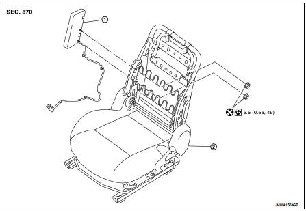
1. Side air bag module 2. Front seat assembly
 : Do not reuse
 : N┬Ęm (kg-m, in-lb)
Removal and Installation
WARNING:
ŌĆó Before servicing, turn ignition switch OFF, disconnect battery negative
terminal and wait 3 minutes
or more.
ŌĆó Always work from the side of air bag module. Never work in front of it.
ŌĆó Never use the air tools or electric tools for servicing.
REMOVAL
1. Remove front seat assembly.
ŌĆó 2WD models: Refer to SE-19, "Removal and Installation".
ŌĆó 4WD models: Refer to SE-27, "Removal and Installation".
2. Remove seatback trim and pad.
ŌĆó 2WD models: Refer to SE-19, "SEATBACK : Disassembly and Assembly".
ŌĆó 4WD models: Refer to SE-27, "SEATBACK : Disassembly and Assembly".
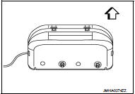
3. Remove side air bag module from seatback trim.
CAUTION
:
ŌĆó Always place the side air bag module with pad side facing
upward.
 : Upward
ŌĆó Never impact the side air bag module.
ŌĆó Replace the side air bag module if it has been dropped or sustained an impact.
ŌĆó Never insert any foreign objects (screwdriver, etc.) into the side air bag module.
ŌĆó Never disassemble the side air bag module.
ŌĆó Never expose the side air bag module to temperatures exceeding 90 ┬░C (194 ┬░F).
ŌĆó Never allow oil, grease, detergent, or water to come in contact with the side air bag module.
INSTALLATION
Note the following items, and then install in the reverse order of removal.
CAUTION:
ŌĆó Never use the old fixing nuts after removal, replace with the new nuts.
ŌĆó Never damage the air bag harness.
ŌĆó If malfunction is detected by the air bag warning lamp, after repair or replacement of the malfunctioning parts, reset the memory using self-diagnosis or CONSULT-III. Refer to SRC-12, "On Board Diagnosis Function" or SRC-16, "CONSULT-III Function".
ŌĆó After the work is completed, check that no system malfunction is detected by air bag warning lamp.
 Front passenger air bag module
Exploded View
1. Front passenger air bag module
2. Instrument panel assembly
: Pawl
: Do not reuse
: N┬Ęm (kg-m, ft-lb)
Removal and Installation
WARNING:
ŌĆó Before servicing, turn ignition ...
 Side curtain air bag module
Exploded View
1. Side curtain air bag module
: Metal clip
: N┬Ęm (kg-m, ft-lb)
Removal and Installation
WARNING:
ŌĆó Before servicing, turn ignition switch OFF, disconnect battery negative
t ...
Other materials:
How to set SRT code
Description
OUTLINE
In order to set all SRTs, the self-diagnoses as in the ŌĆ£SRT ITEMŌĆØ table must
have been performed at least
once. Each diagnosis may require actual driving for a long period of time under
various conditions.
SRT ITEM
The table below shows required self-diagnostic ite ...
B1138, B1139, B1140, B1141, B1142, B1143 diagnosis sensor unit
DTC Logic
DTC DETECTION LOGIC
DTC CONFIRMATION PROCEDURE
1.CHECK SELF-DIAG RESULT
With CONSULT-III
1. Turn ignition switch ON.
2. Perform ŌĆ£Self Diagnostic ResultŌĆØ mode of ŌĆ£AIR BAGŌĆØ using CONSULT-III.
Without CONSULT-III
1. Turn ignition switch ON.
2. Check the air bag warning la ...
Drive belt
Checking
ŌĆó Inspection should be done only when engine is cold or over 30
minutes after the engine is stopped.
1 : Alternator
2 : Water pump
3 : Crankshaft pulley
4 : A/C compressor
5 : Idler pulley
6 : Drive belt
ŌĆó Visually check belts for wear, damage, and cracks on inside and
edge ...
