Nissan Juke Service and Repair Manual : Drive belt
Checking
ÔÇó Inspection should be done only when engine is cold or over 30 minutes after the engine is stopped.
1 : Alternator
2 : Water pump
3 : Crankshaft pulley
4 : A/C compressor
5 : Idler pulley
6 : Drive belt
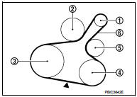
ÔÇó Visually check belts for wear, damage, and cracks on inside and edges.
ÔÇó Turn crankshaft pulley two time clockwise, and check tension on all pulleys is equal before doing the test.
ÔÇó When measuring deflection, apply 98 N (10 kg, 22 lb) at the (
 ) marked point.
ÔÇó Measure the belt tension and frequency with acoustic tension gauge (commercial
service tool) at the ( )
marked point.
CAUTION:
ÔÇó When the tension and frequency are measured, the acoustic tension gauge should
be used.
ÔÇó When checking immediately after installation, first adjust it to the specified value. Then, after turning crankshaft two turns or more, readjust to the specified value to avoid variation in deflection between pulleys.
Belt Deflection/Belt Tension and Frequency: Refer to EM-250, "Drive Belt".
Tension Adjustment

CAUTION:
ÔÇó When belt is replaced with new one, adjust belt tension to the value for ÔÇťNew
beltÔÇŁ, because new belt
will not fully seat in the pulley groove.
ÔÇó When tension of the belt being used exceeds ÔÇťLimitÔÇŁ, adjust it to the value for ÔÇťAfter adjustedÔÇŁ.
ÔÇó When installing a belt, check it is correctly engaged with the pulley groove.
ÔÇó Never allow oil or engine coolant to get on the belt.
ÔÇó Never twist or bend the belt strongly.
1. Remove front fender protector (RH). Refer to EXT-22, "Exploded View".
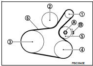
2. After loosening lock nut (A) of idler pulley (5) to release from the specified torque state, temporarily tighten the lock nut to the following torque
 4.4 N┬Ěm (0.45 kg-m, 39 in-lb)
1 : Alternator
2 : Water pump
3 : Crankshaft pulley
4 : A/C compressor
5 : Idler pulley
6 : Drive belt
CAUTION:
ÔÇó When the lock nut is loosened excessively, the idler pulley tilts and the
correct tension adjustment
cannot be performed. Never loosen it excessively (more than 45 degrees).
ÔÇó Put a matching mark on the lock nut (A), and check turning angle with a protractor. Never visually check the tightening angle.
3. Adjust the belt tension by turning the adjusting bolt (B). Refer to EM-154, "Checking".
CAUTION:
ÔÇó When checking immediately after installation, first adjust it to the specified
value. Then, after
turning crankshaft two turns or more, readjust to the specified value to avoid
variation in deflection
between pulleys.
ÔÇó When the tension adjustment is performed, the lock nut should be in the condition at stepÔÇť 2ÔÇŁ. If the tension adjustment is performed when the lock nut is loosened more than the standard, the idler pulley tilts and the correct tension adjustment cannot be performed.
4. Tighten the lock nut.
: 34.8 N┬Ěm (3.5 kg-m, 26 ft-lb)
Removal and Installation
REMOVAL
1. Remove front fender protector (RH). Refer to EXT-22, "Exploded View".
2. Loosen the lock nut (A), and then adjust the belt tension by turning the adjusting bolt (B).
1 : Alternator
2 : Water pump
3 : Crankshaft pulley
4 : A/C compressor
5 : Idler pulley
6 : Drive belt
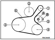
3. Remove drive belt.
INSTALLATION
1. Pull the idler pulley in the loosening direction, and then temporarily tighten the lock nut (A) to the following torque.
1 : Alternator
2 : Water pump
3 : Crankshaft pulley
4 : A/C compressor
5 : Idler pulley
6 : Drive belt
: 4.4 N┬Ěm (0.45 kg-m, 39 in-lb)
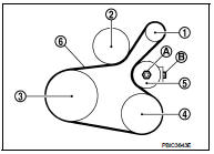
NOTE
:
Do not move the lock nut from the tightened position. Go to step ÔÇť2ÔÇŁ.
2. Install the drive belt to each pulley.
CAUTION:
ÔÇó Check that there is no oil, grease, or coolant, etc. in pulley grooves.
ÔÇó Check that the belt is securely inside the groove on each pulley.
3. Adjust drive belt tension by turning the adjusting bolt (B). Refer to EM-154, "Tension Adjustment".
CAUTION
:
ÔÇó Perform the belt tension adjustment with the lock nut temporarily tightened
at the step ÔÇť1ÔÇŁ so as
not to tilt the idler pulley.
ÔÇó When checking immediately after installation, first adjust it to the specified value. Then, after turning crankshaft two turns or more, readjust to the specified value to avoid variation in deflection between pulleys.
4. Tighten the lock nut.
: 34.8 N┬Ěm (3.5 kg-m, 26 ft-lb)
5. Check that belt tension of each belt within the standard.

 Air cleaner filter
Exploded View
1. Hose clamp
2. PCV hose
3. Hose clamp
4. Air cleaner filter
5. Air cleaner filter case
6. Grommet
7. Inlet Air duct (lower)
8. Grommet
9. Inlet Air duct (upper)
10. B ...
Other materials:
P1642 thermoplunger control unit
DTC Logic
DTC DETECTION LOGIC
Diagnosis Procedure
1.CHECK THERMOPLUNGER CONTROL UNIT POWER SUPPLY CIRCUIT
1. Turn ignition switch OFF.
2. Disconnect thermoplunger control unit harness connector.
3. Check the voltage between thermoplunger control unit harness connector and
ground.
Is the ...
P0850 PNP switch
Description
When the selector lever position is P or N (CVT), Neutral position (M/T),
park/neutral position (PNP) signal is
ON.
DTC Logic
DTC DETECTION LOGIC
DTC CONFIRMATION PROCEDURE
1.INSPECTION START
Do you have CONSULT-III?
Do you have CONSULT-III?
YES >> GO TO 2.
NO >& ...
P1586 G sensor
DTC Logic
DTC DETECTION LOGIC
DTC CONFIRMATION PROCEDURE
CAUTION:
Be careful of the driving speed.
1.PREPARATION BEFORE WORK
If another "DTC CONFIRMATION PROCEDURE" occurs just before, turn ignition
switch OFF and wait for at
least 10 seconds, then perform the next test.
> ...
