Nissan Juke Owners Manual : Fuel-filler cap
To remove the fuel-filler cap:
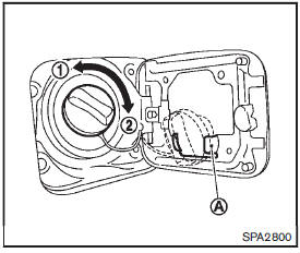
1. Turn the fuel-filler cap counterclockwise 1 to remove.
2. Put the fuel-filler cap on the cap holder A while refueling.
To install the fuel-filler cap:
1. Insert the fuel-filler cap straight into the fuelfiller tube.
2. Turn the fuel-filler cap clockwise 2 until a single click is heard.
WARNING
тАв Gasoline is extremely flammable and highly explosive under certain conditions. You could be burned or seriously injured if it is misused or mishandled. Always stop engine and do not smoke or allow open flames or sparks near the vehicle when refueling.
тАв Do not attempt to top off the fuel tank after the fuel pump nozzle shuts off automatically. Continued refueling may cause fuel overflow, resulting in fuel spray and possibly a fire.
тАв Use only an original equipment type fuel-filler cap as a replacement. It has a built-in safety valve needed for proper operation of the fuel system and emission control system.
An incorrect cap can result in a serious malfunction and possible injury. It could also cause the malfunction indicator light to come on.
тАв Never pour fuel into the throttle body to attempt to start your vehicle.
тАв Do not fill a portable fuel container in the vehicle or trailer. Static electricity can cause an explosion of flammable liquid, vapor or gas in any vehicle or trailer. To reduce the risk of serious injury or death when filling portable fuel containers: тАФ Always place the container on the ground when filling.
тАФ Do not use electronic devices when filling.
тАФ Keep the pump nozzle in contact with the container while you are filling it.
тАФ Use only approved portable fuel containers for flammable liquid.
CAUTION
тАв If fuel is spilled on the vehicle body, flush it away with water to avoid paint damage.
тАв Insert the cap straight into the fuelfiller tube, then tighten until the
fuel-filler cap clicks. Failure to tighten the fuel-filler cap properly may cause
the malfunction  indicator light (MIL)
to illuminate. If the  light illuminates
because the fuelfiller cap is loose or missing, tighten or install the cap and continue
to drive the vehicle. The  light should
turn off after a few driving trips. If the
 light does not turn off after a few
driving trips, have the vehicle inspected by a NISSAN dealer.
For additional information, see тАЬMalfunction Indicator Light (MIL)тАЭ .
тАв The LOOSE FUEL CAP warning message will be displayed if the fuel-filler cap is not properly tightened.
It may take a few driving trips for the message to be displayed.
Failure to tighten the fuel-filler cap properly after the LOOSE FUEL CAP warning
message is displayed may cause the 
Malfunction Indicator Light (MIL) to illuminate.
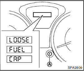
LOOSE FUEL CAP warning message
The LOOSE FUEL CAP warning message is displayed on the vehicle information display when the fuel-filler cap is not tightened correctly after the vehicle has been refueled. It may take a few driving trips for the message to be displayed. To turn off the warning message, do the following procedure:
1. Remove and install the fuel-filler cap as previously described as soon as possible.
2. Tighten the fuel-filler cap until it clicks.
3. Push the trip computer mode switchA for about 1 second to turn off the LOOSE FUEL CAP warning message after tightening the fuel cap.
 Opening the fuel-filler door
To open the fuel-filler door, pull the release handle located below the instrument
panel. To lock, close the fuel-filler door securely. ...
 Tilt steering column
WARNING
Do not adjust the steering wheel while driving. You could lose control of
your vehicle and cause an accident. ...
Other materials:
Back door lock
Exploded View
1. Back door lock assembly 2. TORX bolt 3. Back door striker
: Do not reuse
: N┬╖m (kg-m, ft-lb)
: Body grease
Door lock
DOOR LOCK : Removal and Installation
REMOVAL
1. Remove the back door lower finisher. Refer to INT-35, "BACK DOOR LOWER
FINISHER : Removal and
Insta ...
Front disc brake
Brake pad : Exploded View
MR16DDT
1. Cylinder body
2. Inner shim
3. Inner pad (with pad wear sensor)
4. Pad retainer
5. Torque member
6. Outer pad
7. Outer shim
1: Apply MOLYKOTE┬о AS880N or
silicone-based grease.
2: Apply MOLYKOTE┬о 7439 or
equivalent.
: N┬╖m (kg-m, ft-lb)
HR1 ...
Opening charge port lid
Instrument panel switch
When opening the charge port lid to plug in a charging connector, perform one of the following official interface actions:
Push the physical charge port lid switch located on the lower instrument panel to the left of the steering ...
