Nissan Juke Service and Repair Manual : Back door lock
Exploded View
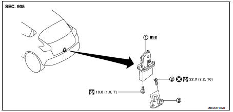
1. Back door lock assembly 2. TORX bolt 3. Back door striker
 : Do not reuse
 : N·m (kg-m, ft-lb)
 : Body grease
Door lock
DOOR LOCK : Removal and Installation
REMOVAL
1. Remove the back door lower finisher. Refer to INT-35, "BACK DOOR LOWER FINISHER : Removal and Installation".
2. Remove back door lock assembly mounting bolts.
3. Disconnect back door lock connector, and then remove back door lock assembly.
INSTALLATION
Note the following item, and install in the reverse order of removal.
CAUTION:
After installation, check back door open/close, and lock/unlock operation.
Emergency lever
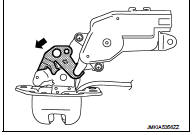
EMERGENCY LEVER : Unlock procedures
UNLOCK PROCEDURES
NOTE
:
If back door lock cannot be unlocked due to a malfunction or battery discharge,
follow the procedures to
unlock back door.
1. Remove emergency lid. Refer to INT-36, "EMERGENCY LID : Removal and Installation".
2. From inside the vehicle, rotate emergency lever toward lower direction and unlock.
 Rear door lock
Exploded View
1. Outside handle assembly
2. Inside handle
3. TORX bolt
4. Door lock assembly
5. Rear door sealing screen
: Clip
: Pawl
: Vehicle front
: Do not reuse
: N·m (kg-m, in-lb ...
 Fuel filler lid opener
Exploded View
1. Fuel filler lid opener cable
2. Cable protector
3. Fuel filler lid lock assembly
4. Fuel filler lid assembly
5. Spring
6. Bumper rubber
: Clip
: Do not reuse
Fuel fille ...
Other materials:
Security indicator lamp does not turn on or blink
Description
Security indicator lamp does not blink when ignition switch is in a position
other than ON.
NOTE:
• Before performing the diagnosis, check “Work Flow”. Refer to SEC-187, "Work
Flow".
• Check that vehicle is under the condition shown in “CONDITIONS OF VEHICLE ...
P0131 A/F sensor 1
DTC Logic
DTC DETECTION LOGIC
To judge the malfunction, the diagnosis checks that the A/F signal computed
by ECM from the A/F sensor 1
signal is not inordinately low.
DTC CONFIRMATION PROCEDURE
1.PRECONDITIONING
If DTC Confirmation Procedure has been previously conducted, always perform
...
Service
• Disconnect battery negative terminal in advance.
• Disconnect air bag system line in advance.
• Never tamper with or force air bag lid open, as this may adversely affect air
bag performance.
• Be careful not to scratch pad and other parts.
• When removing or disassembling any par ...
