Nissan Juke Service and Repair Manual : Fuel filler lid opener
Exploded View
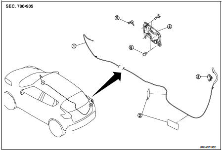
1. Fuel filler lid opener cable
2. Cable protector
3. Fuel filler lid lock assembly
4. Fuel filler lid assembly
5. Spring
6. Bumper rubber
 : Clip
 : Do not reuse
Fuel filler lid
FUEL FILLER LID : Removal and Installation
REMOVAL
1. Fully open fuel filler lid.
2. Remove fuel mounting pin (1).
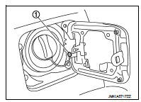
3. Remove mounting screws, and then remove fuel filler lid.
INSTALLATION
Note the following items, and install in the reverse order of removal.
CAUTION:
• After installation, check fuel filler lid assembly open/close, lock/unlock
operation.
• After installation, apply the touch-up paint (the body color) onto the head of the mounting screws.
NOTE
:
• The following table shows the specifide values for checking nomal installation
status.
• Fitting adjustment cannot be perfomed.

Fuel filler opener cable
FUEL FILLER OPENER CABLE : Removal and Installation
REMOVAL
1. Remove hood lock control cable assembly from instrument lower panel (LH). Refer to DLK-471, "HOOD LOCK CONTROL CABLE : Removal and Installation".
2. Remove fuel filler lid opener cable (2) from fuel filler lid opener lever (1).
3. Remove front kicking plate inner (RH) and rear kicking plate inner (RH). Refer to INT-19, "KICKING PLATE INNER : Removal and Installation".
4. Remove dash side finisher (RH). Refer to INT-20, "DASH SIDE FINISHER : Removal and Installation".
5. Remove center pillar lower garnish (RH). Refer to INT-20, "CENTER PILLAR LOWER GARNISH : Removal and Installation".
6. Remove luggage side lower finisher (RH). Refer to INT-31, "LUGGAGE SIDE LOWER FINISHER : Removal and Installation".
7. Remove fuel filler lid opener cable from fuel filler lid lock assembly. Refer to DLK-484, "FUEL FILLER LID LOCK : Removal and Installation".
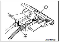
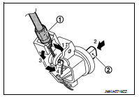
8. Disengage each harness protector (1), and then remove fuel filler lid opener cable (2).
9. Remove fuel filler lid opener cable fixing clips, and then remove fuel filler lid opener cable.
INSTALLATION
Note the following items, and install in the reverse order of removal.
CAUTION:
After installation, check fuel filler lid assembly open/close, lock/unlock
operation.
Fuel filler lid lock
FUEL FILLER LID LOCK : Removal and Installa
REMOVAL
1. Fully open fuel filler lid.
2. Remove luggage side lower finisher (RH). Refer to INT-31, "LUGGAGE SIDE LOWER FINISHER : Removal and Installation".
3. Rotate and disengage fuel filler lid lock assembly, and then remove fuel filler lid lock assembly.
NOTE
:
Operation is performed easily when rotating fuel filler lid lock
from passenger room side.
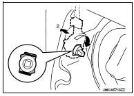
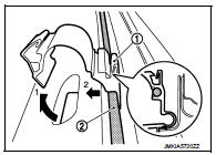
4. Disengage fuel filler lid opener cable (1). Remove fuel filler lid opener cable while pressing stopper pin (2).
INSTALLATION
Note the following item, and install in the reverse order of removal.
CAUTION:
After installation, check fuel filler lid assembly open/close, lock/unlock
operation
.
 Back door lock
Exploded View
1. Back door lock assembly 2. TORX bolt 3. Back door striker
: Do not reuse
: N·m (kg-m, ft-lb)
: Body grease
Door lock
DOOR LOCK : Removal and Installation
REMOVAL
1. Remove ...
 Door switch
Exploded View
1. Door switch
2. TORX bolt
Removal and Installation
REMOVAL
Remove the TORX bolt (A), and then remove door switch (1).
INSTALLATION
Install in the reverse order of removal. ...
Other materials:
B210E starter relay
DTC Logic
DTC DETECTION LOGIC
NOTE:
• If DTC B210E is displayed with DTC U1000, first perform the trouble diagnosis
for DTC U1000. Refer to
PCS-30, "DTC Logic".
• If DTC B210E is displayed with DTC B2605, first perform the trouble diagnosis
for DTC B2605. Refer to
SEC-90, &qu ...
Camshaft
Exploded View
1. Camshaft bracket (No. 2 to 5)
2. Camshaft bracket (No. 1)
3. Camshaft sprocket (EXH)
4.Exhaust valve timing control solenoid
valve
5. O-ring
6.Camshaft sprocket (INT)
7. Plug (EXH)
8. Washer (EXH)
9.Oil filter (for exhaust valve timing control
solenoid valve)
10. ...
IPDM-E branch line circuit
Diagnosis Procedure
1.CHECK CONNECTOR
1. Turn the ignition switch OFF.
2. Disconnect the battery cable from the negative terminal.
3. Check the terminals and connectors of the IPDM E/R for damage, bend and loose
connection (unit side
and connector side).
Is the inspection result normal?
Y ...
