Nissan Juke Service and Repair Manual : Rear door lock
Exploded View
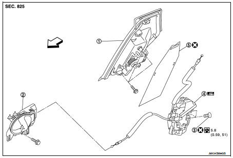
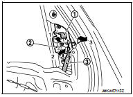
1. Outside handle assembly
2. Inside handle
3. TORX bolt
4. Door lock assembly
5. Rear door sealing screen
 : Clip
 : Pawl
 : Vehicle front
 : Do not reuse
 : N·m (kg-m, in-lb)
 : Body grease
Door lock
DOOR LOCK : Removal and Installation
REMOVAL
1. Remove rear door glass and rear door lower sash (rear). Refer to GW-21, "Removal and Installation".
2. Remove inside handle. Refer to DLK-478, "INSIDE HANDLE : Removal and Installation".
3. Remove outside handle. Refer to DLK-478, "OUTSIDE HANDLE : Removal and Installation".
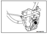
4. Remove door lock assembly TORX bolts.
5. Disconnect door lock actuator connector, and then remove door lock assembly.
INSTALLATION
Note the following items, and install in the reverse order of removal.
CAUTION:
• Never reuse TORX bolt. Always replace it with a new one when it is removed.
• Check door open/close, lock/unlock operation after installation.
• Check door lock assembly for poor lubrication. Apply body grease to door lock if necessary.
 : Grease up point
Inside handle
INSIDE HANDLE : Removal and Installation
REMOVAL
1. Remove rear door finisher. Refer to INT-16, "Removal and Installation".
2. Remove upper side of sealing screen.
NOTE
:
Cut the butyl tape so that some parts of the butyl tape do not remain on the
sealing screen, if the sealing
screen is reused.
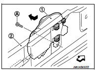
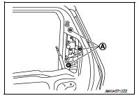
3. Remove inside handle mounting bolt (A).
4. Disengage inside handle (1) from door panel (2) while sliding inside handle toward vehicle rear, and then separate inside handle.
 : Vehicle front
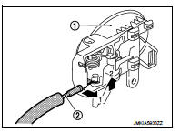
5. Disengage inside handle cable (2), and then remove inside handle (1).
INSTALLATION
Note the following item, and install in the reverse order of removal.
CAUTION:
Check door open/close, lock/unlock operation after installation.
Outside handle
OUTSIDE HANDLE : Removal and Installation
REMOVAL
1. Remove rear door finisher and rear door corner cover inner. Refer to INT-16, "Removal and Installation".
2. Remove rear door sealing screen.
3. Rotate stopper (1) upward.
4. Disengage outside handle cable (2), and then remove outside handle cable from outside handle assembly (3).
5. Remove outside handle assembly mounting bolts (A).
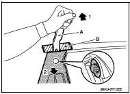
6. Disengage mounting clips using a remover tool (A), and then remove outside handle assembly.
CAUTION:
Apply protective tape (B) on the door panel to protect the
painted surface from damage.
 : Clip
INSTALLATION
Note the following items, and install in the reverse order of removal.
CAUTION:
• Never reuse rear door sealing screen. Always replace it with a new one when it
is removed. When installing rear door sealing screen, install it according to
the following procedure.
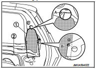
- Put lower portion of rear door sealing screen (1) into inside of door panel (2).
- Perform positioning according to the following procedure, and then install rear door sealing screen.
• Align upper portion of rear door sealing screen to hole (A) of door panel as shown in the figure.
• Align hole of rear door sealing screen to edge (B) of door panel as shown in the figure.
• Be careful to position outside handle cable normally when installing it. For details, refer to DLK-477, "Exploded View".
• Check door open/close, lock/unlock operation after installation.
 Front door lock
Exploded View
1. Door key cylinder assembly (driver
side)
Outside handle escutcheon (passenger
side)
2. Outside handle
3. Front gasket
4. Inside handle
5. TORX bolt
6. Door lock assembly ...
 Back door lock
Exploded View
1. Back door lock assembly 2. TORX bolt 3. Back door striker
: Do not reuse
: N·m (kg-m, ft-lb)
: Body grease
Door lock
DOOR LOCK : Removal and Installation
REMOVAL
1. Remove ...
Other materials:
Avoiding collision and rollover
WARNING
Failure to operate this vehicle in a safe, alert, and prudent manner significantly increases the risk of a dangerous situation and may result in an immediate loss of control or a severe accident.
Be alert, anticipate potential hazards, and drive defensively at all times behind the ...
Brake pedal
Inspection and Adjustment
INSPECTION
Brake Pedal Height
Check the height (H1) between the dash lower panel (1) and the
brake pedal upper surface.
H1 : Refer to BR-70, "Brake Pedal".
CAUTION:
Remove the floor trim.
Stop Lamp Switch
Check the clearance (C) among the brake pedal le ...
NISSAN Advanced Air Bag System (front seats)
1. Crash zone sensor
2. Supplemental front-impact air bag modules
3. Front seat-mounted side-impact supplemental air bag modules
4. Occupant classification sensors (weight sensors)
5. Occupant classification system control unit
6. Roof-mounted curtain side-impact supplemental air bag inflator ...
