Nissan Juke Service and Repair Manual : Front door lock
Exploded View
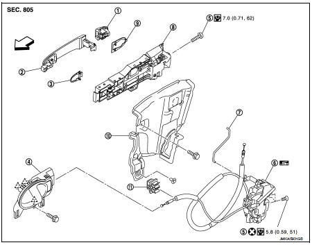
1. Door key cylinder assembly (driver
side)
Outside handle escutcheon (passenger
side)
2. Outside handle
3. Front gasket
4. Inside handle
5. TORX bolt
6. Door lock assembly
7. Key rod (driver side)
8. Outside handle bracket
9. Rear gasket
10. Key rod protector (driver side)
11. Cable clip
 : Pawl
 : Vehicle front
 : Do not reuse
 : N·m (kg-m, in-lb)
 : Body grease
Door lock
DOOR LOCK : Removal and Installation
REMOVAL
1. Remove inside handle. Refer to DLK-474, "INSIDE HANDLE : Removal and Installation".
2. Disengage inside handle cable from cable clip.
3. Remove outside handle bracket. Refer to DLK-474, "OUTSIDE HANDLE : Removal and Installation".
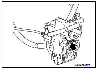
4. Remove door lock assembly TORX bolts.
5. Disconnect door lock actuator connector, and then remove door lock assembly.
INSTALLATION
Note the following items, and install in the reverse order of removal.
CAUTION:
• Never reuse TORX bolt. Always replace it with a new one when it is removed.
• Check door open/close, lock/unlock operation after installation.
• Check door lock cable is properly engaged with outside handle bracket.
• Check door lock assembly for poor lubrication. Apply body grease to door lock if necessary.
 : Grease up point
Inside handle
INSIDE HANDLE : Removal and Installation
REMOVAL
1. Remove front door finisher. Refer to INT-13, "Removal and Installation".
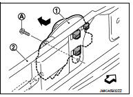
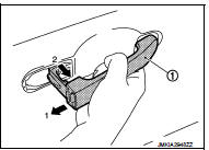
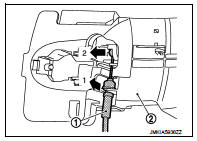
2. Remove inside handle mounting bolt (A).
3. Disengage inside handle (1) from door panel (2) while sliding inside handle toward vehicle rear, and then separate inside handle.
 : Vehicle front
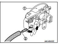
4. Disengage inside handle cable (2), and then remove inside handle (1).
INSTALLATION
Note the following item, and install in the reverse order of removal.
CAUTION:
Check door open/close, lock/unlock operation after installation.
Outside handle
OUTSIDE HANDLE : Removal and Installation
REMOVAL
1. Remove front door glass and front door lower sash (rear). Refer to GW-17, "Removal and Installation".
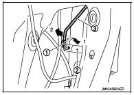
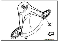
2. Remove key rod protector mounting bolt and fixing clip, and then remove key rod protector.
3. Disengage lock holder (1), and then separate key rod (3) from door lock assembly (2).(Driver side)
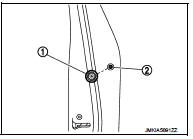
4. Remove grommet (1) of door side. Loosen, through grommet hole, TORX bolt (2) that fixes door lock cylinder. (For passenger side, TORX bolt fixes outside handle escutcheon.)
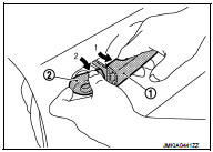
5. While pulling outside handle (1), remove door key cylinder assembly (diver side) (2) or outside handle escutcheon (passenger side) (2).
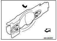
6. While pulling outside handle (1), slide toward rear of vehicle to remove outside handle.
7. Remove front gasket (1) and rear gasket (2).
 : Vehicle front
8. Slide outside handle bracket toward rear of vehicle to remove.
 : Vehicle front
9. Disconnect outside handle cable (1) from outside handle bracket (2).
INSTALLATION
Note the following items, and install in the reverse order of removal.
CAUTION:
• When installing key rod, rotate key rod holder until a click is felt.
• Check that door lock cables are normally engaged with inside handle and outside handle.
• After installation, check door open/close, and lock/unlock operation.
 Hood lock
Exploded View
1. Hood lock control cable assembly
2. Hood lock assembly
: Clip
: N·m (kg-m, ft-lb)
: Body grease
Hood lock
HOOD LOCK : Removal and Installation
REMOVAL
1. Remove front cen ...
 Rear door lock
Exploded View
1. Outside handle assembly
2. Inside handle
3. TORX bolt
4. Door lock assembly
5. Rear door sealing screen
: Clip
: Pawl
: Vehicle front
: Do not reuse
: N·m (kg-m, in-lb ...
Other materials:
Diagnosis system (ECM)
Diagnosis description
Diagnosis description : 1st Trip Detection
Logic and Two Trip Detection Logic
When a malfunction is detected for the first time, 1st trip DTC and 1st trip
Freeze Frame data are stored in the
ECM memory. The MIL will not illuminate at this stage. <1st trip>
If the s ...
P0014 EVT control
DTC Logic
DTC DETECTION LOGIC
NOTE:
If DTC P0014 is displayed with DTC P0078, first perform trouble diagnosis for
DTC P0078. Refer to EC-
585, "DTC Logic".
DTC CONFIRMATION PROCEDURE
1.PRECONDITIONING
If DTC Confirmation Procedure has been previously conducted, always perform
...
Component parts
Component Parts Location
1. Door request switch (driver side)
2. Door mirror (driver side)
3. Remote keyless entry receiver
Refer to DLK-21,
"Component Parts Location"
4. Door mirror remote control switch
5. BCM
Refer to BCS-6, "BODY CONTROL
SYSTEM : Component Parts Loca ...
