Nissan Juke Service and Repair Manual : Front disc brake
Brake pad : Exploded View
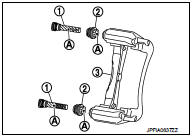
MR16DDT
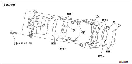
1. Cylinder body
2. Inner shim
3. Inner pad (with pad wear sensor)
4. Pad retainer
5. Torque member
6. Outer pad
7. Outer shim
 1: Apply MOLYKOTE® AS880N or
silicone-based grease.
 2: Apply MOLYKOTE® 7439 or
equivalent.
 : N·m (kg-m, ft-lb)
HR16DE, K9K
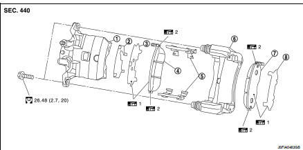
1. Cylinder body
2. Inner shim cover
3. Inner shim
4. Inner pad (with pad wear sensor)
5. Pad retainer
6. Torque member
7. Outer pad 8. Outer shim
1: Apply MOLYKOTE® AS880N or
silicone-based grease.
2: Apply MOLYKOTE® 7439 or
equivalent.
: N·m (kg-m, ft-lb)
Brake pad : Removal and Installation
REMOVAL
WARNING:
Clean any dust from the brake caliper and brake pads with a vacuum dust
collector. Never blow with
compressed air.
CAUTION:
• Never depress the brake pedal while removing the brake pads because the piston
may pop out.
• If the brake fluid or grease adheres to the disc rotor, quickly wipe it off.
1. Remove tires.
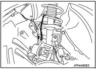
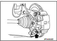
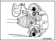
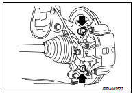
2. Remove lower sliding pin bolt.
3. Suspend the cylinder body with suitable wire so that the brake hose will not stretch.
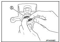
4. Remove the brake pads, shims, shim covers and pad retainers from the torque member.
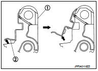
CAUTION:
• Never deform the pad retainer (2) when removing the pad
retainer from the torque member (1).
• Never damage the piston boot.
• Never drop the brake pads, shims, and the shim covers.
• Remember each position of the removed brake pads.
5. Perform inspection after removal. Refer to BR-55, "BRAKE PAD : Inspection".
INSTALLATION
WARNING:
Clean any dust from the brake caliper and brake pads with a vacuum dust
collector. Never blow with
compressed air.
CAUTION:
• Never depress the brake pedal while removing the brake pads or the cylinder
body because the piston
may pop out.
• If the brake fluid or grease adheres to the disc rotor, quickly wipe it off.
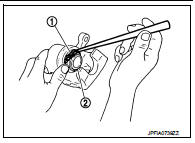
1. Install the pad retainers (1) to the torque member (2) if the pad retainers has been removed.
CAUTION:
• Securely assemble the pad retainers so that it will not be lifted up from the torque member.
• Never deform the pad retainers.
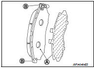
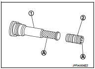
2. Apply MOLYKOTE® AS880N or silicone-based grease to the mating faces (A) between the brake pads and the shims, and install the shims to the brake pad.
CAUTION:
Always replace the shim together with the shim cover when
replacing the brake pad.
3. Apply MOLYKOTE® 7439 or equivalent to the mating faces (B) between the brake pads and the pad retainers.
4. Install the brake pads to the torque member.
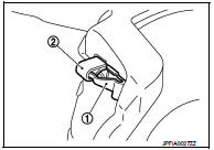
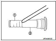
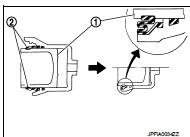
CAUTION:
• Both inner and outer pads have a pad return system on
the pad retainer. Install pad return lever (1) securely to pad
retainer (2).
• Never deform the pad retainers.
5. Install cylinder body to torque member.
CAUTION:
• Never damage the piston boot.
• When replacing brake pad with new one, check a brake fluid level in the reservoir tank because brake fluid returns to master cylinder reservoir tank when pressing piston in.
NOTE:
Use a disc brake piston tool to easily press piston.
6. Install the lower sliding pin bolt and tighten it to the specified torque.
7. Depress the brake pedal several times to check that no drag feel is present for the front disc brake. Refer to BR-55, "BRAKE PAD : Inspection".
8. Install tires. Refer to WT-7, "Exploded View".
Brake pad : Inspection
INSPECTION AFTER REMOVAL
• Replace the shims and the shim covers if rust is excessively attached.
• Eliminate rust on the pad retainers and the torque member. Replace them if rust is excessively attached.
INSPECTION AFTER INSTALLATION
1. Check a drag of rear disc brake. If any drag is found, follow the procedure described below.
2. Remove brake pads. Refer to BR-62, "BRAKE PAD : Removal and Installation".
3. Press the pistons. Refer to BR-62, "BRAKE PAD : Removal and Installation".
4. Install brake pads. Refer to BR-62, "BRAKE PAD : Removal and Installation".
5. Securely depress the brake pedal several times.
6. Check a drag of rear disc brake again. If any drag is found, disassemble the cylinder body and replace if necessary. Refer to BR-66, "BRAKE CALIPER ASSEMBLY : Disassembly and Assembly" 7. Burnish contact surfaces brake pads and disc rotor after refinishing or replacing brake pads, or if a soft pedal occurs at very low mileage. Refer to BR-18, "BRAKE PAD : Inspection and Adjustment".
Brake caliper assembly : Exploded View
REMOVAL
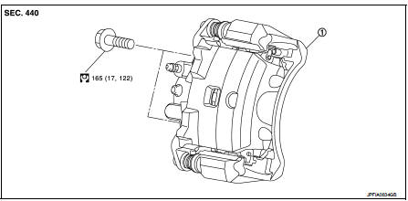
1. Brake caliper assembly
 : N·m (kg-m, ft-lb)
DISASSEMBLY
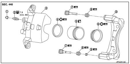
1. Cap
2. Bleeder valve
3. Cylinder body
4. Piston seal
5. Piston
6. Piston boot
7. Sliding pin
8. Sliding pin boot
9. Bushing
10. Torque member
 : Apply rubber grease.
 : Apply brake fluid.
 : N·m (kg-m, in-lb)
 Always replace after every
disassembly.
Brake caliper assembly : Removal and Installation
REMOVAL
WARNING:
Clean any dust from the brake caliper and brake pads with a vacuum dust
collector. Never blow with
compressed air.
CAUTION:
• Never spill or splash brake fluid on painted surfaces. Brake fluid may
seriously damage paint. Wipe it
out immediately and wash with water if it gets on a protect surface. For brake
component parts,
never wash them with water.
• Never depress the brake pedal while removing the brake hose. If this is not complied with, brake fluid may splash.
• Never drop removed parts.
• If the brake fluid or grease adheres to the disc rotor, quickly wipe it off.
1. Remove tires.
2. Fix the disc rotor using wheel nuts.
3. Drain brake fluid. Refer to BR-12, "Draining".
4. Separate brake hose from caliper assembly. Refer to BR-29, "FRONT : Removal and Installation".
5. Remove torque member mounting bolts, and remove brake caliper assembly.
CAUTION:
Never drop brake pad and caliper assembly.
6. When removing disc rotor.
• MR16DDT: Refer to FAX-11, "Removal and Installation".
• HR16DE: Refer to FAX-43, "Removal and Installation".
• K9K: Refer to FAX-68, "Removal and Installation".
INSTALLATION
WARNING:
Clean any dust from the brake caliper and brake pads with a vacuum dust
collector. Never blow with
compressed air.
CAUTION:
• Never spill or splash brake fluid on painted surfaces. Brake fluid may
seriously damage paint. Wipe it
out immediately and wash with water if it gets on a protect surface. For brake
component parts,
never wash them with water.
• Never depress the brake pedal while removing the brake hose. If this is not complied with, brake fluid may splash.
• If the brake fluid or grease adheres to the disc rotor, quickly wipe it off.
1. Install disc rotor.
• MR16DDT: Refer to FAX-11, "Removal and Installation".
• HR16DE: Refer to FAX-43, "Removal and Installation".
• K9K: Refer to FAX-68, "Removal and Installation".
2. Install the brake caliper assembly to the steering knuckle and tighten the torque member mounting bolts to the specified torque.
CAUTION:
Never spill or splash any grease and moisture on the brake
caliper assembly mounting face, threads, mounting bolts
and washers. Wipe out any grease and moisture.
3. Install brake hose. Refer to BR-29, "FRONT : Removal and Installation".
4. Perform the air bleeding. Refer to BR-13, "Bleeding Brake System".
5. Check a drag of front disc brake. If any drag is found, refer to BR-60, "BRAKE CALIPER ASSEMBLY : Inspection".
6. Install tires. Refer to WT-7, "Exploded View".
7. Perform inspection after installation. Refer to BR-60, "BRAKE CALIPER ASSEMBLY : Inspection".
Brake caliper assembly : Disassembly and Assembly
DISASSEMBLY
NOTE
:
Never remove the torque member, brake pad and pad retainers when disassembling
and assembling the cylinder
body.
1. Remove the sliding pin bolt, and remove the cylinder body from the torque member. Refer to BR-54, "BRAKE PAD : Removal and Installation".
CAUTION:
Fix the brake pad at suitable tape so that the brake pad will not drop.
2. Remove sliding pins and sliding pin boots from torque member.
3. Remove bushing (1) from sliding pin (2).
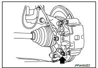
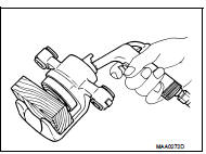
4. Place a wooden block as shown in the figure, and blow air from union bolt mounting hole to remove pistons and piston boots.
CAUTION:
Never get fingers caught in the pistons.
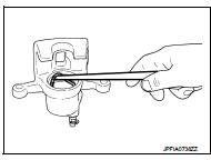
5. Remove piston seal from cylinder body using seal pick tool.
CAUTION:
Be careful not to damage a cylinder inner wall.
6. Remove bleeder valve and cap.
7. Perform inspection after disassembly. Refer to BR-60, "BRAKE CALIPER ASSEMBLY : Inspection".
ASSEMBLY
1. Install bleeder valve and cap.
2. Apply rubber grease to piston seals (1), and install them to cylinder body.
CAUTION:
Never reuse piston seals.
3. Apply rubber grease to piston boots (1). Cover the piston (2) end with piston boot, and then install cylinder side lip on piston boot securely into a groove on cylinder body.
CAUTION:
Never reuse piston boots.
4. Apply new brake fluid to pistons (1). Push piston into cylinder body by hand and push piston boot (2) piston-side lip into the piston groove.
CAUTION:
Press the pistons evenly and vary the pressing point to prevent
cylinder inner wall from being rubbed.
5. Apply rubber grease to mating faces (A) between sliding pin (1) and bushing (2), and install bushing to sliding pin.
6. Apply rubber grease to mating faces (A) between sliding pin (1) and sliding pin boot (2), and install sliding pin and sliding pin boot to sliding torque member (3).
7. Install the cylinder body to tighten cylinder body mounting bolts to the specified torque. Refer to BR-53, "BRAKE PAD : Exploded View".
Brake caliper assembly : Inspection
INSPECTION AFTER DISASSEMBLY
Check the following items and replace if necessary.
Cylinder Body
Check the inner wall of the cylinder for rust, wear, cracks or damage.
CAUTION
:
Always clean with new brake fluid. Never clean with mineral oil such as
gasoline and light oil.
Torque Member
Check the torque member for rust, wear, cracks or damage.
Pistons
Check the surface of the piston for rust, wear, cracks or damage.
CAUTION:
A piston sliding surface is plated. Never polish with sandpaper.
Sliding Pin, Sliding Pin Boot and Bushing Check the sliding pins, sliding boots and bushing for rust, wear, cracks or damage.
INSPECTION AFTER INSTALLATION
1. Check a drag of front disc brake. If any drag is found, follow the procedure described below.
2. Remove brake pads. Refer to BR-54, "BRAKE PAD : Removal and Installation".
3. Press the pistons. Refer to BR-54, "BRAKE PAD : Removal and Installation".
4. Install brake pads. Refer to BR-54, "BRAKE PAD : Removal and Installation".
5. Securely depress the brake pedal several times.
6. Check a drag of front disc brake again. If any drag is found, disassemble the cylinder body and replace if necessary. Refer to BR-58, "BRAKE CALIPER ASSEMBLY : Disassembly and Assembly".
7. Burnish contact surface between disc rotor and brake pads after refinishing or replacing disc rotor, or if a soft pedal occurs at very low mileage. Refer to BR-18, "DISC ROTOR : Inspection and Adjustment".
 Vacuum lines
MR16DDT : Exploded View
1. Clamp
2. Vacuum hose A
3. Vacuum piping
4. Vacuum hose B
A. To engine side
B. Paint mark C. To brake booster
MR16DDT : Removal and Installation
REMOVAL
1. Remo ...
 Rear disc brake
Brake pad : Exploded View
1. Sliding pin bolt
2. Cylinder body
3. Inner shim cover
4. Inner shim
5. Inner pad (with pad wear sensor)
6. Pad retainer
7. Torque member
8. Outer pad
9. O ...
Other materials:
Door motor
Exploded View
LEFT SIDE
1. A/C unit assembly
2. Intake door lever
3. Intake door link
4. Intake door motor
5. Air mix door motor
6. Air mix door link
7. Max. cool door
8. Upper air mix door lever
9. Air mix door rod
10. Lower air mix door lever
RIGHT SIDE
1. A/C unit assembly ...
Appearance and care
Removing spots
To preserve the pristine finish of your Nissan Leaf, it is essential to remove stubborn contaminants such as road tar, oil splatters, industrial fallout, insect residue, and tree sap as promptly as possible. If left to sit, these substances can chemically bond with or etch the pa ...
Water pump
Exploded View
1. Gasket
2. Water pump
3. Water pump pulley
: Always replace after every
disassembly.
: N·m (kg-m, in-lb)
: N·m (kg-m, ft-lb)
Removal and Installation
REMOVAL
1. Drain engine coolant from radiator. Refer to CO-37, "Draining".
CAUTION:
• Perform this st ...
