Nissan Juke Service and Repair Manual : Vacuum lines
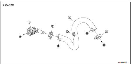
MR16DDT : Exploded View
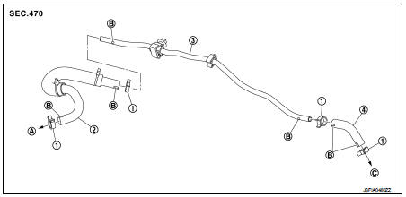
1. Clamp
2. Vacuum hose A
3. Vacuum piping
4. Vacuum hose B
A. To engine side
B. Paint mark C. To brake booster
MR16DDT : Removal and Installation
REMOVAL
1. Remove air duct and air cleaner case. Refer to EM-161, "Removal and Installation".
2. Remove the vacuum hose and vacuum piping.
3. Perform inspection after removal. Refer to BR-49, "MR16DDT : Inspection".
INSTALLATION
Note the following, install the vacuum hose.
• When installing vacuum hose, insert it until its tip reaches the back-end of length (A) or further as shown in the figure.
CAUTION:
Never use lubricating oil during assembly.
A : 24 mm (0.95 in) or mor
- Face the paint mark of vacuum hose A (engine side) upward to assemble.
- Face the other paint marks to vehicle front side to assemble.
- For clamp mounting direction (the orientation of pawl), refer to BR- 49, "MR16DDT : Exploded View".
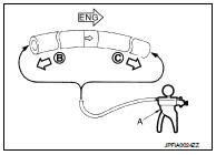
MR16DDT : Inspection
INSPECTION AFTER REMOVAL
Appearance
Check for correct assembly, damage and deterioration.
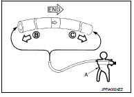
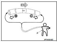
Check Valve Airtightness • Use a handy vacuum pump (A) to check.
When connected to the booster side (B): Vacuum should decrease within 1.3 kPa (9.8 mmHg, 0.38 inHg, 0.013 bar) for 15 seconds under a vacuum of −66.7 kPa (−500 mmHg, −19.70 inHg, −0.667 bar).
When connected to the engine side (C): Vacuum should not exist.
• Replace vacuum hose if vacuum hose is malfunctioning.
HR16DE : Exploded View
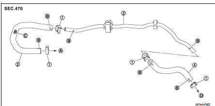
1. Clamp
2. Vacuum hose (built-in check valve)
3. Vacuum piping
4. Vacuum hose
A. To intake manifold
B. Paint mark
C. Stamp indicating engine direction
D. To brake booster
HR16DE : Removal and Installation
REMOVAL
1. Remove air duct and air cleaner case. Refer to EM-161, "Removal and Installation".
2. Remove the vacuum hose and vacuum piping.
3. Perform inspection after removal. Refer to BR-51, "HR16DE : Inspection".
INSTALLATION
Note the following, install the vacuum hose
• When installing vacuum hose, insert it until its tip reaches the back-end of length (A) or further as shown in the figure.
CAUTION:
Never use lubricating oil during assembly.
A : 24 mm (0.95 in) or more
- Face the paint mark of vacuum hose (built-in check valve, intake manifold side) upward to assemble.
- Face the other paint marks to vehicle front side to assemble.
- For clamp mounting direction (the orientation of pawl), refer to BR- 50, "HR16DE : Exploded View".
HR16DE : Inspection
INSPECTION AFTER REMOVAL
Appearance
Check for correct assembly, damage and deterioration.
Check Valve Airtightness • Use a handy vacuum pump (A) to check.
When connected to the booster side (B): Vacuum should decrease within 1.3 kPa (9.8 mmHg, 0.38 inHg, 0.013 bar) for 15 seconds under a vacuum of −66.7 kPa (−500 mmHg, −19.70 inHg, −0.667 bar).
When connected to the engine side (C): Vacuum should not exist.
• Replace vacuum hose assembly if vacuum hose and check valve are malfunctioning.
K9K : Exploded View
1. Connector
2. Clamp
3. Vacuum hose (built-in check valve)
A. To vacuum pump
B. Paint mark
C. Stamp indicating engine direction
D. To brake booster
K9K : Removal and Installation
REMOVAL
1. Remove air duct and air cleaner case. Refer to EM-161, "Removal and Installation".
2. Remove the vacuum hose and connector.
3. Perform inspection after removal. Refer to BR-52, "K9K : Inspection".
INSTALLATION
Note the following, install the vacuum hose.
• When installing vacuum hose, insert it until its tip reaches the back-end of length (A) or further as shown in the figure.
CAUTION:
Never use lubricating oil during assembly.
A : 24 mm (0.95 in) or more
- Face the paint mark of vacuum hose (built-in check valve, connector side) to the vehicle left side to assemble.
- Face the paint mark of vacuum hose (built-in check valve, brake booster side) to the front side to assemble.
- For clamp mounting direction (the orientation of pawl), refer to BR- 51, "K9K : Exploded View".
K9K : Inspection
INSPECTION AFTER REMOVAL
Appearance
Check for correct assembly, damage and deterioration.
Check Valve Airtightness • Use a handy vacuum pump (A) to check.
When connected to the booster side (B): Vacuum should decrease within 1.3 kPa (9.8 mmHg, 0.38 inHg, 0.013 bar) for 15 seconds under a vacuum of −66.7 kPa (−500 mmHg, −19.70 inHg, −0.667 bar).
When connected to the engine side (C): Vacuum should not exist.
• Replace vacuum hose assembly if vacuum hose and check valve are malfunctioning.
 Brake booster
Exploded View
2WD
1. Master cylinder assembly
2. Vacuum pipe
3. Brake booster
4. Lock nut
5. Clevis
6. Gasket
7. Spacer
: N·m (kg-m, ft-lb)
4WD
1. Master cylinder assembly
2. Bra ...
 Front disc brake
Brake pad : Exploded View
MR16DDT
1. Cylinder body
2. Inner shim
3. Inner pad (with pad wear sensor)
4. Pad retainer
5. Torque member
6. Outer pad
7. Outer shim
1: Apply MOLYKOTE® AS88 ...
Other materials:
Precaution Necessary for Steering Wheel Rotation after Battery Disconnect
NOTE:
• Before removing and installing any control units, first turn the ignition
switch to the LOCK position, then disconnect
both battery cables.
• After finishing work, confirm that all control unit connectors are connected
properly, then re-connect both
battery cables.
• Always us ...
Brake pedal
Exploded View
WITHOUT ESP
1. Clevis pin
2. Brake pedal assembly
3. Brake pedal pad
4. Stop lamp switch
5. Clip
6. Snap pin
: Apply multi-purpose grease.
: N·m (kg-m, ft-lb)
WITH ESP
1. Clevis pin
2. Brake pedal assembly
3. Brake pedal pad
4. Brake switch/brake pedal position ...
P183E yaw rate sensor
DTC Logic
DTC DETECTION LOGIC
DTC CONFIRMATION PROCEDURE
1.PRECONDITIONING
If “DTC CONFIRMATION PROCEDURE” has been previously conducted, always turn
ignition switch OFF and
wait at least 10 seconds before conducting the next test.
>> GO TO 2.
2.DTC REPRODUCTION PROCEDURE
W ...
