Nissan Juke Service and Repair Manual : Structure and operation
Sectional View
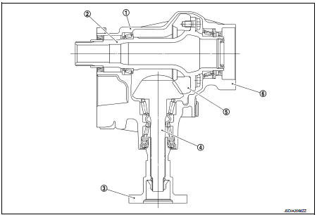
1. Transfer cover
2. Ring gear shaft
3. Companion flange
4. Drive pinion
5. Ring gear
6. Transfer case
Operation Principle
POWER TRANSFER DIAGRAM
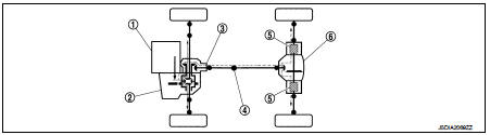
1. Engine
2. Transaxle
3. Transfer
4. Propeller shaft
5. Electric controlled coupling
6. Rear final drive
ELECTRIC CONTROLLED COUPLING
1. The 4WD control module supplies command current to each electric controlled coupling (4WD solenoid).
2. Each of control clutch is engaged by electromagnet and torque is detected in control clutch.
3. The cam operates in response to control clutch torque and applies pressure to main clutch.
4. Each of main clutch transmits torque to right and left rear wheels according to pressing power.
NOTE
:
Change each pressing power according to 4WD mode atatus
and cornering conditions
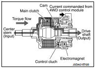
• Transmission torque to the right and left rear wheels is determined according to command current.
 Component parts
Component Parts Location
LHD models
1. ABS actuator and electric unit (control
unit)
Refer to BRC-97, "Component Parts
Location".
2. ECM
Refer to EC-25, "ENGINE CONTROL
SYSTEM ...
 System
4WD system : System Diagram
INPUT/OUTPUT SIGNAL
It transmits/receives each signal from the following 4WD control module via
CAN communication line.
4WD system : System Description
• 4WD ...
Other materials:
Sill cover
Exploded View
1. Screw grommet
2. Screw grommet
3. Sill cover
4. Wind defle
Removal and Installation
REMOVAL
1. Remove sill cover front end fixing screw (A).
2. Remove sill cover rear end fixing screw (A).
3. Remove sill cover lower side fixing screws.
4. Fully open front door and ...
Rear door
Exploded View
1. Rear door panel
2. TORX bolt
3. Door striker
4. Door check link
5. Door hinge (lower)
6. Door hinge (upper)
: Do not reuse
: N·m (kg-m, in-lb)
: N·m (kg-m, ft-lb)
: Body grease
Door assembly
DOOR ASSEMBLY : Removal and Installation
CAUTION:
• Perform work wit ...
Precaution for Supplemental Restraint System (SRS) "AIR BAG" and "SEAT BELT
PRE-TENSIONER"
The Supplemental Restraint System such as “AIR BAG” and “SEAT BELT PRE-TENSIONER”,
used along
with a front seat belt, helps to reduce the risk or severity of injury to the
driver and front passenger for certain
types of collision. Information necessary to service the system safely is
...
