Nissan Juke Service and Repair Manual : Air cleaner filter
Exploded View
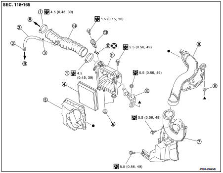
1. Hose clamp
2. PCV hose
3. Hose clamp
4. Air cleaner filter
5. Air cleaner filter case
6. Grommet
7. Inlet Air duct (lower)
8. Grommet
9. Inlet Air duct (upper)
10. Bracket
11. Air cleaner case
12. O-ring
13. Mass air flow sensor
14. Air duct
A. To electric throttle control actuator B. To rocker cover
 : Always replace after every
disassembly.
 : N·m (kg-m, in-lb)
Removal and Installation
REMOVAL
1. Remove the assembly consisting of element case, air cleaner case, and inlet air duct (upper).
2. Remove the air cleaner filter case.
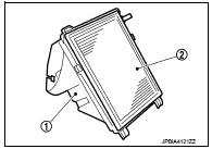
3. Remove the air cleaner filter (2) from the air cleaner case (1).
INSTALLATION
Note the following, and install in the reverse order of removal.
• Check by the feel and the sound that both pawls of the air cleaner case are securely fastened to the element case.
 Drive belt
Checking
• Inspection should be done only when engine is cold or over 30
minutes after the engine is stopped.
1 : Alternator
2 : Water pump
3 : Crankshaft pulley
4 : A/C compressor
5 : Idler ...
 Spark plug
Removal and Installation
REMOVAL
1. Remove ignition coil. Refer to EM-178, "Exploded View".
2. Remove spark plug with a spark plug wrench (commercial service
tool).
a : 14 mm (0.55 in) ...
Other materials:
Cooling fan
Component Function Check
1.CHECK COOLING FAN FUNCTION
With CONSULT-III
1. Turn ignition switch ON.
2. Perform “FAN DUTY CONTROL” in “ACTIVE TEST” mode of “ENGINE” using
CONSULT-III.
3. Check that cooling fan speed varies according to the percentage.
Without CONSULT-III
1. Acti ...
BCM (body control module)
Removal and Installation
CAUTION:
Before replacing BCM, perform “READ CONFIGURATION” to save or print current
vehicle specification.
Refer to BCS-150, "Description".
REMOVAL (RHD MODELS)
1. Remove glove box assembly. Refer to IP-13, "Removal and Installation".
2. Re ...
Keyfob ID registration
Description
Perform the following procedure after BCM is replaced or when new keyfob ID
is registered
NOTE:
When registering the keyfob ID, perform only one procedure to simultaneously
register both ID (IMMOBILIZER
ID and keyfob ID).
Work Procedure
1.STEP 1
Close all doors.
>> GO ...
