Nissan Juke Service and Repair Manual : Front bumper
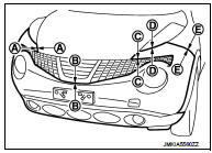
Exploded View
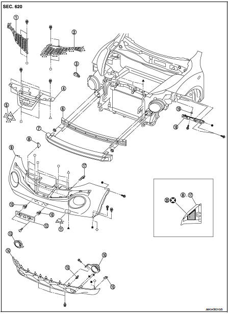
1. Front side grille RH
2. Front side grille LH
3. Bumper side bracket RH
4. Front center grille
5. Emblem
6. Bumper reinforcement
7. Energy absorber
8. Bumper end rubber RH
9. Bumper fascia
10. Screw grommet
11. Bumper bracket cover
12. License plate bracket
13. Front fog bracket RH
14. Bumper fascia lower
15. U nut
16. Front fog bracket LH
17. Bumper end rubber LH
18. Bumper side bracket LH
19. Screw grommet
20. double-sided tape
[t: 1.2 mm (0.047 in)]
 : Pawl
 : Do not reuse
Removal and Installation
CAUTION:
Bumper fascia is made of resin. Never apply strong force to it, and be careful
to prevent contact with
oil.
REMOVAL
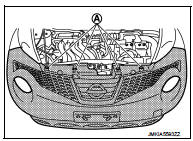
1. Fully open hood assembly.
2. Remove clips (A) of bumper upper side.
3. Remove front fillet molding front side. Refer toEXT-26, "FRONT FILLET MOLDING : Removal and Installation".
4. Remove bumper fascia assembly fixing screws (A) (LH and RH).
5. Remove air guide fixing screws, and then remove air guide (LH and RH).Refer to EXT-22, "Exploded View".
6. Remove clips of bumper lower side.
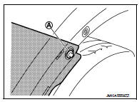
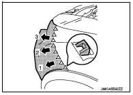
7. Pull bumper fascia side toward the vehicle side to disengage the fitting of bumper side bracket and bumper fascia side as shown by the arrow in the figure.
 : Pawl
8. CAUTION:
When removing bumper fascia assembly, 2 workers are
required so as to prevent it from dropping.
9. Disconnect front fog lamp harness connectors. (with fog lamp) 10. Remove bumper fascia assembly.
11. Remove the following parts after removing bumper fascia assembly.
• Front fog lamp assembly (LH and RH). (with fog lamp)
• Front fog lamp finishers (LH and RH). (with out fog lamp)
• Bumper fascia lower
• License plate bracket
12. Remove bumper energy absorber.
13. Remove bumper reinforcement mounting nuts, and then remove bumper reinforcement.
14. Remove bumper side bracket mounting screws, and then remove bumper side bracket.
INSTALLATION
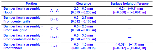
Note the following items, and then install in the reverse order of removal.
NOTE
:
• The following table shows the specified values for checking normal
installation status.
• Fitting adjustment cannot be performed.

 Rear bumper
Exploded View
1. Bumper side bracket LH
2. Bumper closing LH
3. Bumper fascia assembly
4. Reflex reflector LH
5. Rear panel lower
6. U nut
7. Bumper fascia lower
8. Reflex reflector RH ...
Other materials:
System
Can communication system
CAN COMMUNICATION SYSTEM : System Diagram
CAN COMMUNICATION SYSTEM : System Description
Description
• CAN (Controller Area Network) is a serial communication line for real time
application. It is an on-vehicle
multiplex communication line with high data communicat ...
ABS branch line circuit
Diagnosis Procedure
1.CHECK CONNECTOR
1. Turn the ignition switch OFF.
2. Disconnect the battery cable from the negative terminal.
3. Check the terminals and connectors of the ABS actuator and electric unit
(control unit) for damage, bend
and loose connection (unit side and connector side).
...
System
Relay control system
RELAY CONTROL SYSTEM : System Diagram
*1: Except for MR16DDT engine models
*2: For MR16DDT engine models
RELAY CONTROL SYSTEM : System Description
IPDM E/R activates the internal control circuit to perform the relay ON-OFF
control according to the input signals
from va ...
