Nissan Juke Service and Repair Manual : B2556 Push-button ignition switch
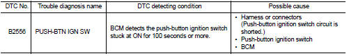
DTC Logic
DTC DETECTION LOGIC
DTC CONFIRMATION PROCEDURE
1.PERFORM DTC CONFIRMATION PROCEDURE
1. Press push-button ignition switch under the following condition.
- Brake pedal: Not depressed 2. Release push-button ignition switch and wait 100 seconds or more.
3. Check DTC in “Self Diagnostic Result” mode of “BCM” using CONSULT-III.
Is DTC detected? YES >> Go to SEC-76, "Diagnosis Procedure".
NO >> INSPECTION END
Diagnosis Procedure
1.CHECK PUSH-BUTTON IGNITION SWITCH INPUT SIGNAL
1. Turn ignition switch OFF.
2. Disconnect push-button ignition switch connector.
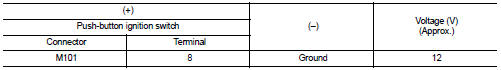
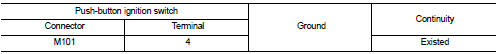
3. Check voltage between push-button ignition switch harness connector and ground.
Is the inspection result normal? YES >> GO TO 4.
NO >> GO TO 2.
2.CHECK PUSH-BUTTON IGNITION SWITCH CIRCUIT
1. Disconnect BCM connector and IPDM E/R connector.
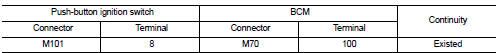
2. Check continuity between push-button ignition switch harness connector and BCM harness connector.
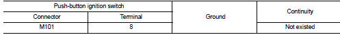
3. Check continuity between push-button ignition switch harness connector and ground.
Is the inspection result normal? YES >> GO TO 3.
NO >> Repair or replace harness.
3.REPLACE BCM
1. Replace BCM. Refer to BCS-93, "Removal and Installation".
2. Perform initialization of BCM and registration of all Intelligent Keys using CONSULT-III.
For initialization and registration procedures, refer to CONSULT-III Operation Manual NATS-IVIS/NVIS.
>> INSPECTION END
4.CHECK PUSH-BUTTON IGNITION SWITCH GROUND CIRCUIT
Check continuity between push-button ignition switch harness connector and ground.
Is the inspection result normal? YES >> GO TO 5.
NO >> Repair or replace harness.
5.CHECK PUSH-BUTTON IGNITION SWITCH
Refer to SEC-77, "Component Inspection".
Is the inspection result normal? YES >> GO TO 6.
NO >> Replace push-button ignition switch. Refer to SEC-168, "Removal and Installation".
6.CHECK INTERMITTENT INCIDENT
Refer to GI-42, "Intermittent Incident".
>> INSPECTION END
Component Inspection
1.CHECK PUSH-BUTTON IGNITION SWITCH
1. Turn ignition switch OFF.
2. Disconnect push-button ignition switch connector.
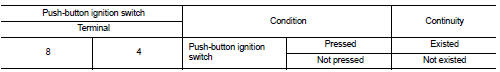
3. Check continuity between push-button ignition switch terminals.
Is the inspection result normal? YES >> INSPECTION END
NO >> Replace push-button ignition switch. Refer to SEC-168, "Removal and Installation".
 B2555 stop lamp
DTC Logic
DTC DETECTION LOGIC
DTC CONFIRMATION PROCEDURE
1.PERFORM DTC CONFIRMATION PROCEDURE
1. Depress the brake pedal and wait 1 second or more.
2. Check DTC in “Self Diagnostic Result” ...
 B2557 vehicle speed
DTC Logic
DTC DETECTION LOGIC
NOTE:
• If DTC B2557 is displayed with DTC U1000, first perform the trouble diagnosis
for DTC U1000. Refer to
BCS-83, "DTC Logic".
• If DTC B2557 is ...
Other materials:
The light reminder warning does not sound
Description
Light reminder warning chime does not sound even though headlamp is
illuminated.
Diagnosis Procedure
1.CHECK COMBINATION SWITCH (LIGHTING SWITCH) OPERATION
Check that the headlamps operate normally by operating the combination switch
(lighting switch).
Do they operate normally ...
Precaution Necessary for Steering Wheel Rotation after Battery Disconnect
NOTE:
• Before removing and installing any control units, first turn the ignition
switch to the LOCK position, then disconnect
both battery cables.
• After finishing work, confirm that all control unit connectors are connected
properly, then re-connect both
battery cables.
• Always us ...
P0710 transmission fluid temperature sensor A
DTC Logic
DTC DETECTION LOGIC
DTC CONFIRMATION PROCEDURE
CAUTION:
Always drive vehicle at a safe speed.
NOTE:
If “DTC CONFIRMATION PROCEDURE” has been previously performed, always turn
ignition switch
OFF and wait at least 10 seconds before performing the next test.
After the repai ...
