Nissan Juke Service and Repair Manual : P0225 APP sensor
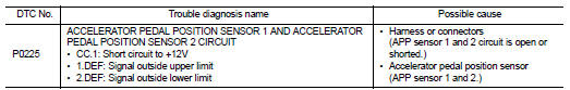
DTC Logic
DTC DETECTION LOGIC
NOTE
:
• If DTC P0225 is displayed with DTC P0641, first perform trouble diagnosis for
DTC P0641. Refer to
EC-974, "DTC Logic".
Diagnosis Procedure
1.CHECK GROUND CONNECTIONS
1. Turn ignition switch OFF.
2. Check ground connection E38. Refer to Ground inspection in GI-44, "Circuit Inspection".
Is the inspection result normal? YES >> GO TO 2.
NO >> Repair or replace ground connection.
2.CHECK ACCELERATOR PEDAL POSITION SENSOR POWER SUPPLY CIRCUIT
1. Disconnect accelerator pedal position sensor harness connector.
2. Turn ignition switch ON.
3. Check the voltage between accelerator pedal position sensor connector and ground
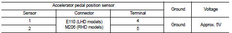
Is the inspection result normal? YES >> GO TO 4.
NO >> GO TO 3.
3.DETECT MALFUNCTIONING PART
• Harness connectors M77, E105 (RHD models) • Harness connectors M95, M202 (RHD models) • Harness for open or short between ECM and accelerator pedal position sensor
>> Repair open circuit or short to ground or short to power in harness or connector.
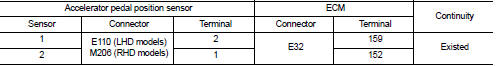
4.CHECK ACCELERATOR PEDAL POSITION SENSOR GROUND CIRCUIT FOR OPEN AND SHORT
1. Turn ignition switch OFF.
2. Disconnect ECM harness connector.
3. Check the continuity between accelerator pedal position sensor harness connector and ECM harness connector.
4. Also check harness for short to ground and short to power.
Is the inspection result normal? YES >> GO TO 6.
NO >> GO TO 5.
5.DETECT MALFUNCTIONING PART
• Harness connectors M77, E105 (RHD models) • Harness connectors M95, M202 (RHD models) • Harness for open or short between ECM and accelerator pedal position sensor
>> Repair open circuit or short to ground or short to power in harness or connector.
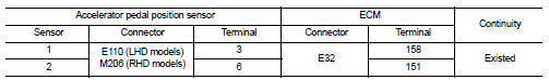
6.CHECK ACCELERATOR PEDAL POSITION SENSOR INPUT SIGNAL CIRCUIT FOR OPEN AND SHORT
1. Check the continuity between accelerator pedal position sensor harness connector and ECM harness connector.
2. Also check harness for short to ground and short to power.
Is the inspection result normal? YES >> GO TO 8.
NO >> GO TO 7.
7.DETECT MALFUNCTIONING PART
• Harness connectors M77, E105 (RHD models) • Harness connectors M95, M202 (RHD models) • Harness for open or short between ECM and accelerator pedal position sensor
>> Repair open circuit or short to ground or short to power in harness or connector.
8.CHECK ACCELERATOR PEDAL POSITION SENSOR
Refer to EC-926, "Component Inspection".
Is the inspection result normal? YES >> GO TO 9.
NO >> Replace accelerator pedal position sensor.
9.CHECK INTERMITTENT INCIDENT
Refer to GI-42, "Intermittent Incident", ???INCIDENT SIMULATION TESTS??? and ???GROUND INSPECTION???.
>> INSPECTION END
Component Inspection
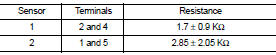
1.CHECK ACCELERATOR PEDAL POSITION SENSOR
1. Turn ignition switch OFF.
2. Disconnect accelerator pedal position sensor harness connector.
3. Check resistance between accelerator pedal position sensor as follows.
Is the inspection result normal?
YES >> INSPECTION END
NO >> Replace accelerator pedal position sensor.
 P0217 engine over temperature
DTC Logic
DTC DETECTION LOGIC
If the cooling fan or another component in the cooling system malfunctions,
engine coolant temperature will
rise.
When the engine coolant temperature reaches an a ...
 P0226 APP sensor
DTC Logic
DTC DETECTION LOGIC
Diagnosis Procedure
1.CHECK GROUND CONNECTIONS
1. Turn ignition switch OFF.
2. Check ground connection E38. Refer to Ground inspection in GI-44, "Circuit
In ...
Other materials:
Door request switch
Component Function Check
1.CHECK FUNCTION
1. Select “INTELLIGENT KEY” of “BCM” using CONSULT-III.
2. Select “REQ SW-DR”, “REQ SW-AS” in “DATA MONITOR” mode.
3. Check that the function operates normally according to the following
conditions.
Is the inspection result norma ...
General Precautions
WARNING:
When replacing fuel line parts, be sure to observe the following.
• Put a “CAUTION: FLAMMABLE” sign in the workshop.
• Be sure to work in a well ventilated area and furnish workshop with a CO2 fire
extinguisher.
• Never smoke while servicing fuel system. Keep open flames a ...
Liquid Gasket
REMOVAL OF LIQUID GASKET SEALING
• After removing mounting nuts and bolts, separate the mating surface
using the seal cutter [SST: KV10111100] (A) and remove old
liquid gasket sealing.
CAUTION:
Be careful not to damage the mating surfaces.
• Tap the seal cutter [SST: KV10111100] to inser ...
