Nissan Juke Service and Repair Manual : P0524 engine oil pressure
DTC Logic
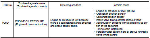
DTC DETECTION LOGIC
NOTE
:
If DTC P0524 is displayed with DTC P0520 or P0075, perform trouble diagnosis for
DTC P0520 or P0075
first. Refer to EC-674, "DTC Logic" or EC-583, "DTC Logic".
DTC CONFIRMATION PROCEDURE
1.PRECONDITIONING
If DTC Confirmation Procedure has been previously conducted, always perform the following procedure before conducting the next test.
1. Turn ignition switch OFF and wait at least 10 seconds.
2. Turn ignition switch ON.
3. Turn ignition switch OFF and wait at least 10 seconds.
TESTING CONDITION:
Before performing the following procedure, confirm that battery voltage is
between 10 V and 16 V at
idle.
>> GO TO 2.
2.PRECONDITIONING-II
Check oil level and oil pressure. Refer to LU-25, "Inspection".
Is the inspection result normal? YES >> GO TO 3.
NO >> Proceed to LU-25, "Inspection".
3.PERFORM DTC CONFIRMATION PROCEDURE
 WITH CONSULT-III
1. Select ÔÇťDATA MONITORÔÇŁ mode of ÔÇťENGINEÔÇŁ using CONSULT-III.
2. Maintain the following conditions for at least 20 consecutive seconds.
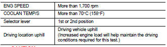
CAUTION:
Always drive at a safe speed.
3. Check 1st trip DTC.
 WITH GST
Follow the procedure ÔÇťWith CONSULT-IIIÔÇŁ above.
Is 1st trip DTC detected? YES >> Proceed to EC-679, "Diagnosis Procedure" NO >> INSPECTION END
Diagnosis Procedure
1.CHECK OIL PRESSURE WARNING LAMP
1. Start engine.
2. Check oil pressure warning lamp and confirm it is not illuminated.
Is oil pressure warning lamp illuminated? YES >> Proceed to LU-25, "Inspection".
NO >> GO TO 2.
2.CHECK INTAKE VALVE TIMING CONTROL SOLENOID VALVE
Refer to EC-584, "Component Inspection".
Is the inspection result normal? YES >> GO TO 3.
NO >> Replace malfunctioning intake valve timing control solenoid valve. Refer to EM-181, "Exploded View".
3.CHECK CRANKSHAFT POSITION SENSOR
Refer to EC-658, "Component Inspection".
Is the inspection result normal? YES >> GO TO 4.
NO >> Replace crankshaft position sensor. Refer to EM-169, "Exploded View".
4.CHECK CAMSHAFT POSITION SENSOR
Refer to EC-662, "Component Inspection".
Is the inspection result normal? YES >> GO TO 5.
NO >> Replace malfunctioning camshaft position sensor. Refer to EM-178, "Exploded View".
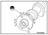
5.CHECK CAMSHAFT (INT)
Check the following.
ÔÇó Accumulation of debris to the signal plate of camshaft rear end ÔÇó Chipping signal plate of camshaft rear end
Is the inspection result normal? YES >> GO TO 6.
NO >> Remove debris and clean the signal plate of camshaft rear end or replace camshaft. Refer to EM-191, "Exploded View".
6.CHECK TIMING CHAIN INSTALLATION
Check service records for any recent repairs that may cause timing chain misaligned.
Are there any service records that may cause timing chain misaligned? YES >> Check timing chain installation. Refer to EM-181, "Exploded View".
NO >> GO TO 7.
7.CHECK LUBRICATION CIRCUIT
Perform ÔÇťInspection of Camshaft Sprocket (INT) Oil GrooveÔÇŁ. Refer to EM-200, "Inspection".
Is the inspection result normal? YES >> Check intermittent incident. refer to GI-42, "Intermittent Incident".
NO >> Clean lubrication line.
 P0520 EOP sensor
DTC Logic
DTC DETECTION LOGIC
DTC CONFIRMATION PROCEDURE
1.PRECONDITIONING
If DTC Confirmation Procedure has been previously conducted, always perform
the following procedure
before conductin ...
 P0603 ECM
Description
ECM has the memory function of the DTC memory, the air-fuel ratio
feedback compensation value memory, the Idle Air Volume Learning
value memory, etc. even when the ignition switch is tu ...
Other materials:
Electric foldable door mirror does not operate
Diagnosis Procedure
1.CHECK DOOR MIRROR (OPEN/CLOSE MOTOR) CIRCUIT
Check door mirror (open/close motor) circuit.
Refer to MIR-25, "Component Function Check".
Is the inspection result normal?
YES >> GO TO 2.
NO >> Repair or replace the malfunctioning parts.
2.CONF ...
Front door lock
Exploded View
1. Door key cylinder assembly (driver
side)
Outside handle escutcheon (passenger
side)
2. Rear gasket
3. Outside handle bracket
4. TORX bolt
5. Key rod (driver side)
6. Door lock assembly
7. Inside handle
8. Outside handle
9. Front gasket
10. Cable clip
: Pawl
: V ...
B1146 curtain air bag module RH
DTC Logic
DTC DETECTION LOGIC
DTC CONFIRMATION PROCEDURE
1.CHECK SELF-DIAG RESULT
With CONSULT-III
1. Turn ignition switch ON.
2. Perform ÔÇťSelf Diagnostic ResultÔÇŁ mode of ÔÇťAIR BAGÔÇŁ using CONSULT-III.
Without CONSULT-III
1. Turn ignition switch ON.
2. Check the air bag warning la ...
