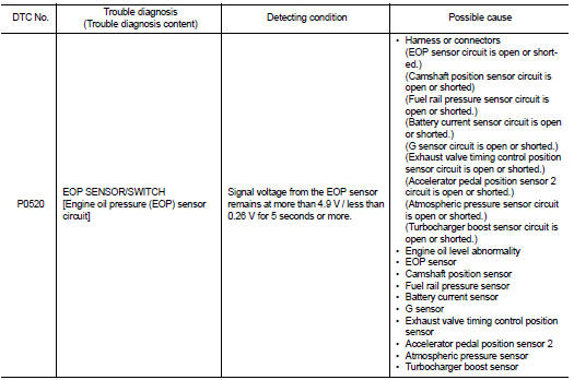
Nissan Juke Service and Repair Manual : P0520 EOP sensor
DTC Logic
DTC DETECTION LOGIC
DTC CONFIRMATION PROCEDURE
1.PRECONDITIONING
If DTC Confirmation Procedure has been previously conducted, always perform the following procedure before conducting the next test.
1. Turn ignition switch OFF and wait at least 10 seconds.
2. Turn ignition switch ON.
3. Turn ignition switch OFF and wait at least 10 seconds.
>> GO TO 2.
2.PERFORM DTC CONFIRMATION PROCEDURE
1. Turn ignition switch ON and wait at least 5 seconds.
2. Check 1st trip DTC.
Is 1st trip DTC detected? YES >> Proceed to EC-674, "Diagnosis Procedure".
NO >> INSPECTION END
Diagnosis Procedure
1.CHECK ENGINE OIL
1. Turn ignition switch OFF.
2. Check engine oil level and pressure. Refer to LU-8, "Inspection".
Is inspection result normal? YES >> GO TO 2.
NO >> Repair or replace error-detected parts.
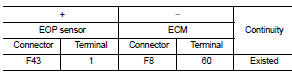
2.CHECK EOP SENSOR POWER SUPPLY-I
1. Disconnect EOP sensor connector.
2. Turn ignition switch ON.
3. Check the voltage between EOP sensor harness connector terminals.
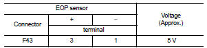
Inspection result normal? YES >> GO TO 7.
NO >> GO TO 3.
3.CHECK EOP SENSOR POWER SUPPLY-II
Check the voltage between EOP sensor harness connector and the ground.
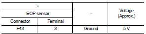
Is inspection result normal? YES >> GO TO 5.
NO >> GO TO 4.
4.CHECK SENSOR POWER SUPPLY CIRCUIT
1. Turn ignition switch OFF.
2. Disconnect ECM harness connector.
3. Check harness connector for short to power and short to ground, between the following terminals
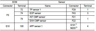
*1: LHD models or RHD with CVT models *2: RHD with M/T models
Is inspection result normal? YES >> Perform the trouble diagnosis for power supply circuit.
NO >> Repair or replace error-detected parts.
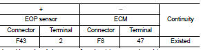
5.CHECK EOP SENSOR GROUND CIRCUIT
1. Turn ignition switch OFF.
2. Disconnect ECM harness connector.
3. Check the continuity between EOP sensor harness connector and ECM harness connector.
4. Also check harness for short to power.
Is inspection result normal? YES >> GO TO 6.
NO >> Repair or replace error-detected parts.
6.CHECK ECM GROUND CIRCUIT
Check the continuity between ECM harness connector and ground.
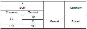
Is inspection result normal? YES >> Check intermittent incident. Refer to GI-42, "Intermittent Incident".
NO >> Repair or replace error-detected parts.
7.CHECK EOP SENSOR SIGNAL CIRCUIT
1. Turn ignition switch OFF.
2. Disconnect ECM harness connector.
3. Check the continuity between EOP sensor harness connector and ECM harness connector.
4. Also check harness for short to ground and to power.
Is inspection result normal? YES >> GO TO 8.
NO >> Repair or replace error-detected parts.
8.CHECK EOP SENSOR
Refer to EC-676, "Component Inspection".
Is inspection result normal? YES >> Check intermittent incident. Refer to GI-42, "Intermittent Incident".
NO >> Repair or replace error-detected parts.
Component Inspection
1.CHECK EOP SENSOR
1. Turn ignition switch OFF.
2. Disconnect EOP sensor harness connector.
3. Check resistance between EOP sensor connector terminals.
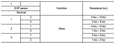
Is the inspection result normal? YES >> INSPECTION END.
NO >> Replace EOP sensor. Refer to EM-103, "Exploded View".
 P0500 VSS
Description
The vehicle speed signal is sent to the combination meter from the “ABS
actuator and electric unit (control
unit)” by CAN communication line. The combination meter then sends a sig ...
 P0524 engine oil pressure
DTC Logic
DTC DETECTION LOGIC
NOTE:
If DTC P0524 is displayed with DTC P0520 or P0075, perform trouble diagnosis for
DTC P0520 or P0075
first. Refer to EC-674, "DTC Logic" or EC-583, & ...
Other materials:
Key reminder function does not operate
Diagnosis Procedure
1.CHECK DOOR LOCK AND UNLOCK SWITCH
Check door lock and unlock switch.
Refer to DLK-520, "Component Function Check".
Is the inspection result normal?
YES >> GO TO 2.
NO >> Repair or replace the malfunctioning parts.
2.CHECK KEY SWITCH
Check k ...
Tire chains
Use of tire chains may be prohibited according to location. Check the local laws
before installing tire chains. When installing tire chains, make sure they are the
proper size for the tires on your vehicle and are installed according to the chain
manufacturer’s suggestions. Use only SAE Clas ...
Warning/Indicator lights (red)
12-volt battery charge warning light
Your Nissan Leaf utilizes a sophisticated DC/DC converter system, which is responsible for stepping down the high-voltage energy from the 400-volt Li-ion main battery to effectively maintain and charge the vehicle's standard 12-volt battery. ...
