Nissan Juke Service and Repair Manual : Combination switch input circuit
Diagnosis Procedure
1.CHECK INPUT 1 - 5 CIRCUIT FOR OPEN
1. Turn ignition switch OFF.
2. Disconnect BCM and combination switch connectors.
3. Check continuity between BCM harness connector and combination switch harness connector.
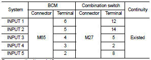
Does continuity exist? YES >> GO TO 2.
NO >> Repair harnesses or connectors.
2.CHECK INPUT 1 - 5 CIRCUIT FOR SHORT
Check for continuity between BCM harness connector and ground.
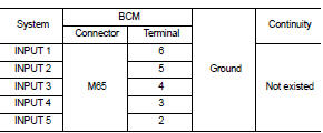
Does continuity exist? YES >> Repair harnesses or connectors.
NO >> GO TO 3.
3.CHECK BCM INPUT SIGNAL
1. Connect BCM and combination switch connectors.
2. Turn ON any switch in the system that is malfunction.
3. Check voltage between BCM harness connector and ground.
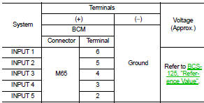
Is the measurement value normal? Yes >> Replace BCM. Refer to BCS-161, "Removal and Installation".
No >> Replace combination switch.
 Combination switch output circuit
Diagnosis Procedure
1.CHECK OUTPUT 1 - 5 CIRCUIT FOR OPEN
1. Turn ignition switch OFF.
2. Disconnect BCM and combination switch connectors.
3. Check continuity between BCM harness connector and co ...
 Symptom diagnosis
COMBINATION SWITCH SYSTEM SYMPTOMS
Symptom Table
1. Perform ŌĆ£Data MonitorŌĆØ of CONSULT-III to check for any malfunctioning
item.
2. Check the malfunction combinations.
3. Identify the malfu ...
Other materials:
Rear drive shaft
Exploded View
1. Circular clip
2. Dust shield
3. Housing
4. Snap ring
5. Ball cage/steel ball/inner race assembly
6. Stopper ring
7. Boot band
8. Boot
9. Shaft
10. Joint sub-assembly
11. Sensor rotor
: Wheel side
: Fill NISSAN genuine grease or an
equivalent.
: Always replace ...
RearView Monitor system operation
The automated RearView Monitor system is programmed to automatically display a live wide-angle view of the area directly behind the vehicle on the central console screen as soon as the shift selector is placed into the R (Reverse) position. The audio system radio playback or me ...
ProPILOT Assist system operation
Steering-wheel-mounted control (left): Dedicated to managing vehicle settings and menu navigation.
Vehicle information display: The primary interface for viewing system status, alerts, and active driver assistance graphics.
Steering-wheel-mounted con ...
