Nissan Juke Service and Repair Manual : Combination switch output circuit
Diagnosis Procedure
1.CHECK OUTPUT 1 - 5 CIRCUIT FOR OPEN
1. Turn ignition switch OFF.
2. Disconnect BCM and combination switch connectors.
3. Check continuity between BCM harness connector and combination switch harness connector
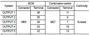
Does continuity exist? YES >> GO TO 2.
NO >> Repair harnesses or connectors.
2.CHECK OUTPUT 1 - 5 CIRCUIT FOR SHORT
Check for continuity between BCM harness connector and ground.
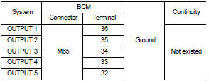
Does continuity exist? YES >> Repair harnesses or connectors.
NO >> GO TO 3.
3.CHECK BCM OUTPUT VOLTAGE
1. Connect BCM connector.
2. Check voltage between BCM harness connector and ground.
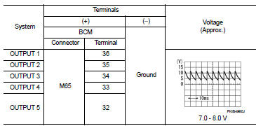
Is the measurement value normal?
YES >> Replace combination switch.
NO >> Replace BCM. Refer to BCS-161, "Removal and Installation".
 Power supply and ground circuit
Diagnosis Procedure
1.CHECK FUSES AND FUSIBLE LINK
Check that the following fuses and fusible link are not fusing.
Is the fuse fusing?
YES >> Replace the blown fuse or fusible link after r ...
 Combination switch input circuit
Diagnosis Procedure
1.CHECK INPUT 1 - 5 CIRCUIT FOR OPEN
1. Turn ignition switch OFF.
2. Disconnect BCM and combination switch connectors.
3. Check continuity between BCM harness connector and com ...
Other materials:
IPDM-E branch line circuit
Diagnosis Procedure
1.CHECK CONNECTOR
1. Turn the ignition switch OFF.
2. Disconnect the battery cable from the negative terminal.
3. Check the terminals and connectors of the IPDM E/R for damage, bend and loose
connection (unit side
and connector side).
Is the inspection result normal?
Y ...
Reference Value
VALUES ON THE DIAGNOSIS TOOL
Remarks:
• Specification data are reference values.
• Specification data are output/input values
which are detected or supplied by the ECM at the connector.
* Specification data may not be directly related to their components
signals/values/operations.
I ...
Crash zone sensor
Exploded View
1. Crash zone sensor
2. Bracket
: Vehicle front
: Do not reuse
N·m (kg-m, ft-lb)
Removal and Installation
WARNING:
• Before servicing, turn ignition switch OFF, disconnect battery negative
terminal and wait 3 minutes
or more.
• Never use the air tools or electric to ...
