Nissan Juke Service and Repair Manual : Operation
Switch Name and Function
OPERATION AND DISPLAY
A/C Display (Display in Multi Display Unit)
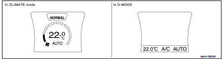
• Air conditioning system operation status is indicated on display in multi display unit. Indication of air conditioning system varies according to display mode of multi display unit. For changing procedure of display mode, refer to AV-99, "NISSAN DYNAMIC CONTROL SYSTEM : System Description".
- In CLIMATE mode: Operation status of air conditioning system (setting temperature, air flow, and “AUTO”*1) is indicated on display when air conditioning system is turned ON.
- In D-MODE: Operation status of air conditioning system (setting temperature, A/C switch, and “AUTO”*2) is indicated on lower portion of display when air conditioning system is turned ON.
NOTE
:
*1: AUTO is indicated when both air flow and air outlet are in automatic
control.
*2: Air Flow is indicated when air flow or air outlet is in manual control.
A/C Controller (Multi Display Unit) Operation procedure of air conditioning system varies depending on display mode of multi display unit. For changing procedure of display mode, refer to AV-99, "NISSAN DYNAMIC CONTROL SYSTEM : System Description".
• In CLIMATE mode: All operations of air conditioning system are possible.
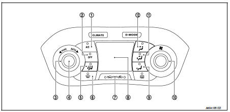
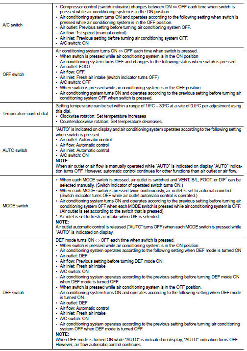
1. A/C switch
2. OFF switch
3. Temperature control dial
4. AUTO switch
5. MODE switch (D/F)
6. DEF switch
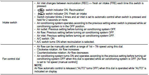
7. Intake switch
8. Display
9. MODE switch (FOOT)
10. Fan control dial
11. MODE switch (B/L)
12. MODE switch (VENT)
• In D-MODE: The following switches and dial cannot be operated.
- A/C switch
- OFF switch
- MODE switch
- Fan control dial
 System
Automatic air conditioning system : System Diagram
Automatic air conditioning system : System Description
DESCRIPTION
• Automatic air conditioning system is controlled by each function of A/C
...
 Diagnosis system (A/C auto AMP.)
Description
Air conditioning system performs self-diagnosis, operation check, function
diagnosis, and various settings
using diagnosis function of each control unit.
CONSULT-III Function
CONSU ...
Other materials:
P183B solenoid power supply
DTC Logic
DTC DETECTION LOGIC
DTC CONFIRMATION PROCEDURE
1.PRECONDITIONING
If “DTC CONFIRMATION PROCEDURE” has been previously conducted, always turn
ignition switch OFF and
wait at least 10 seconds before conducting the next test.
>> GO TO 2.
2.DTC REPRODUCTION PROCEDURE
W ...
Door does not lock/unlock with keyfob
Diagnosis Procedure
1.CHECK POWER DOOR LOCK OPERATION
Check power door lock operation.
Does door lock/unlock with door lock and unlock switch?
YES >> GO TO 2.
NO >> Go to DLK-415, "ALL DOOR : Diagnosis Procedure".
2.CHECK REMOTE KEYLESS ENTRY RECEIVER
Check remote ...
How to use brightness control and display ON/OFF button
To change the display brightness, push the
button. Pushing the button again will
change the display to the day or the night display.
If no operation is performed within 5 seconds, the display will return to the
previous display.
Push and hold the button for more
than two seconds to turn t ...
