Nissan Juke Service and Repair Manual : Diagnosis system (A/C auto AMP.)
Description
Air conditioning system performs self-diagnosis, operation check, function diagnosis, and various settings using diagnosis function of each control unit.
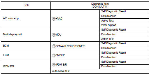
CONSULT-III Function
CONSULT-III performs the following functions via CAN communication with A/C auto amp.
NOTE
:
Diagnosis should be performed with engine running. Door motor operation speeds
become slower and NO
results may be returned even for normal operation if battery voltage drops below
12 V during self-diagnosis.
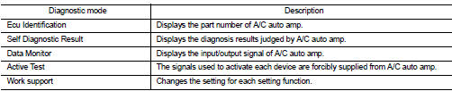
ECU IDENTIFICATION
Part number of A/C auto amp. can be checked.
SELF-DIAGNOSIS RESULTS
Diagnosis result that is judged by A/C auto amp. can be checked. Refer to HAC-130, "DTC Index".
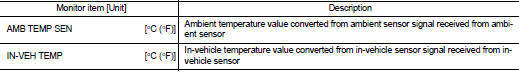
DATA MONITOR
Input/output signal of A/C auto amp. can be checked.
Display item list
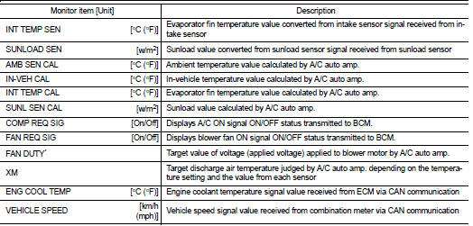
*: ÔÇťDUTYÔÇŁ is displayed, but voltage is indicated. Or unit is not displayed but unit is (V).
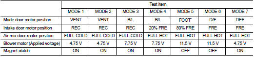
ACTIVE TEST
The signals used to activate each device forcibly supplied from A/C auto amp. operation check of air conditioning system can be performed.

Check each output device
NOTE
:
Perform the inspection of each output device after starting the engine because
the compressor is operated.
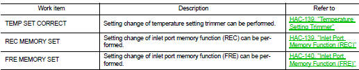
WORK SUPPORT
Setting change of each setting functions can be performed.
NOTE
:
When the battery cable is disconnected from the negative terminal or when the
battery voltage becomes 10 V
or less, the setting of WORK SUPPORT may be cancelled.
 Operation
Switch Name and Function
OPERATION AND DISPLAY
A/C Display (Display in Multi Display Unit)
ÔÇó Air conditioning system operation status is indicated on display in multi
display unit. Indication ...
 Diagnosis system (BCM) (with intelligent key system)
Common item : consult-III Function (BCM - COMMON ITEM)
APPLICATION ITEM
CONSULT-III performs the following functions via CAN communication with BCM.
SYSTEM APPLICATION
BCM can perform the follow ...
Other materials:
P0130 A/F sensor 1
DTC Logic
DTC DETECTION LOGIC
To judge the malfunction, the diagnosis checks that the A/F signal computed
by ECM from the A/F sensor 1
signal fluctuates according to fuel feedback control.
DTC CONFIRMATION PROCEDURE
1.PRECONDITIONING
If DTC Confirmation Procedure has been previously conduc ...
Radiator core supporT
HR16DE
HR16DE : Exploded View
1. Radiator core support upper
2. Air guide RH (MT models)
3. Radiator core support lower
4. Air guide LH
5. Air guide (upper)
6. Air guide LH (CVT models)
7. Air guide RH (CVT models)
: N┬Ěm (kg-m, ft-lb)
HR16DE : Removal and Installation
RADIATOR CORE ...
Service Equipment
RECOVERY/RECYCLING RECHARGING EQUIPMENT
Be certain to follow the manufacturerÔÇÖs instructions for machine operation
and machine maintenance. Never
introduce any refrigerant other than that specified into the machine.
ELECTRICAL LEAK DETECTOR
Be certain to follow the manufacturerÔÇÖs instruc ...
