Nissan Juke Service and Repair Manual : Component parts
Manual air conditioning system : Component Part Location
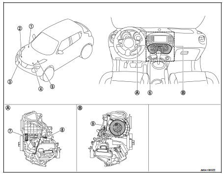
1. BCM
• With Intelligent Key: Refer to BCS-
6, "BODY CONTROL SYSTEM :
Component Parts Location".
• Without Intelligent Key: Refer to BCS-161, "Removal and Installation".
2. Magnet clutch
3. Refrigerant pressure sensor
4. ECM
• HR16DE: Refer to EC-455, "ENGINE
CONTROL SYSTEM :
Component Parts Location".
• MR16DDT: Refer to EC-25, "ENGINE CONTROL SYSTEM : Component Parts Location".
• K9K: Refer to EC-813, "Component Parts Location".
5. IPDM E/R
• With Intelligent Key: Refer to PCS-
5, "Component Parts Location".
• Without Intelligent Key: Refer to PCS-37, "Component Parts Location".
6. A/C control
7. Blower fan resistor
8. Thermo control amp.
9. Blower motor
A. Left side of A/C unit assembly B. Right side of A/C unit assembly
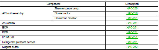
Manual air conditioning system : Component Description
PTC heater control system : Component Parts Location
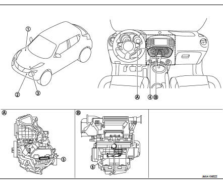
1. BCM
• With Intelligent Key: Refer to BCS-
6, "BODY CONTROL SYSTEM :
Component Parts Location".
• Without Intelligent Key: Refer to BCS-161, "Removal and Installation".
2. Ambient sensor
3. ECM
Refer to EC-813.
4. A/C control
5. PTC heater
6. PTC heater control unit
A. Left side of A/C unit assembly B. Back side of A/C unit assembly
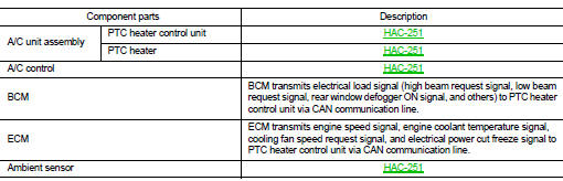
PTC heater control system : Component Description
A/C unit assembly : Thermo Control Amp.
• Thermo control amp. is composed of thermistor and amplifier. Thermistor is installed on evaporator, and amplifier is attached to foot duct.
• When the thermistor detecting temperature of the evaporator fin is extremely low, thermo control amp. sends the thermo control amp. OFF signal to BCM, and stops the compressor.
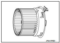
A/C unit assembly : Blower Motor
• The blower motor utilizes a brush-less motor with a rotating magnet.
• Quietness is improved over previous motors where the brush was the point of contact and the coil rotated.
A/C unit assembly : Blower Fan Resistor
• Compact and lightweight resistor is adopted with outstanding ventilation.
• Temperature fuse is installed to protects the blower motor circuit.
A/C unit assembly : PTC Heater Control Unit
• The PTC heater control unit consists of a microcomputer and connectors for signal input and output and for power supply. The PTC heater control unit controls PTC heater system.
• Self-diagnosis functions are also built into PTC heater control unit to provide quick check of malfunctions in the PTC heater control system.
A/C unit assembly : PTC Heater
Heat element is heated and air flow temperature is increased by power supply from PTC relay.
A/C Control
Controls the air conditioning function.
BCM
BCM transmits A/C ON signal and blower fan ON signal to ECM via CAN communication, according to A/C switch signal and blower fan ON signal that are received from A/C control and thermo control amp. signal that is received from thermo control amp. and A/C indicator is turned ON.
ECM
ECM, when receiving A/C ON signal and blower fan ON signal from BCM, transmits A/C compressor request signal to IPDM E/R via CAN communication according to status of the engine and refrigerant pressure.
IPDM E/R
A/C relay is integrated in IPDM E/R. IPDM E/R operates A/C relay when A/C compressor request signal is received from ECM via CAN communication line.
Ambient Sensor
Ambient sensor measures ambient air temperature. The sensor uses a thermistor which is sensitive to the change in temperature. The electrical resistance of the thermistor decreases as temperature increases.
Refrigerant Pressure Sensor
DESCRIPTION
• The refrigerant pressure sensor converts high-pressure side refrigerant pressure into voltage and outputs it to ECM.
• ECM operates cooling system protection and idle speed control according to voltage value that is input.
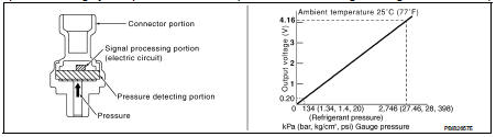
STRUCTURE AND OPERATION
• The refrigerant pressure sensor is a capacitance type sensor. It consists of a pressure detection ares and a signal processing area.
• The pressure detection area, which is a variable capacity condenser, changes internal static capacitance according to pressure force.
• The signal processing area detects the static capacitance of the pressure detection area, converts the static capacitance into a voltage value, and transmits the voltage value to ECM.
Magnet Clutch
Compressor is driven by the magnet clutch which is magnetized by electric power supply.

 System
Manual air conditioning system : System Diagram
Manual air conditioning system : System Description
DESCRIPTION
• Manual air conditioning system is controlled by each function of thermo
contr ...
Other materials:
Wiring diagram
POWER DISTRIBUTION SYSTEM
LHD
LHD : Wiring Diagram
For connector terminal arrangements, harness layouts, and alphabets in a
(option abbreviation; if not
described in wiring diagram), refer to GI-12, "Connector Information/Explanation
of Option Abbreviation".
RHD
RHD : Wiring D ...
Additional service when removing battery negative terminal
Description
When the battery negative terminal is disconnected, the initialization is
necessary for normal operation of
power window system.
CAUTION:
The following specified operations can not be performed under the
non-initialized condition.
• Auto-up operation
• Anti-pinch function ...
Head restraints/headrests
WARNING
Head restraints and headrests are vital components of your vehicle's safety architecture, designed to work in concert with other safety systems. They provide essential support that can significantly reduce the risk of neck and spinal injuries during certain rear-end collisions.
...
