Nissan Juke Service and Repair Manual : System
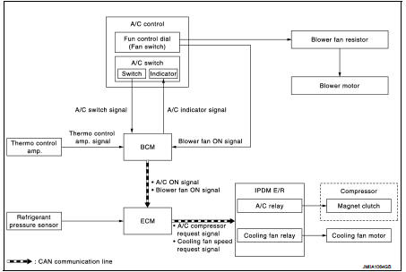
Manual air conditioning system : System Diagram
Manual air conditioning system : System Description
DESCRIPTION
• Manual air conditioning system is controlled by each function of thermo control amp., BCM, ECM and IPDM E/R.
• Fan speed of blower motor is changed by the combination of fan control dial operation and blower fan resistor control.
CONTROL BY THERMO CONTROL AMP.
• HAC-253, "MANUAL AIR CONDITIONING SYSTEM : Compressor Control"
CONTROL BY BCM
• HAC-253, "MANUAL AIR CONDITIONING SYSTEM : Compressor Control"
CONTROL BY ECM
• HAC-253, "MANUAL AIR CONDITIONING SYSTEM : Compressor Control"
• Cooling fan control
- HR16DE: Refer to EC-479, "COOLING FAN CONTROL : System Description".
- MR16DDT: Refer to EC-61, "COOLING FAN CONTROL : System Description".
- K9K: Refer to EC-827, "COOLING FAN CONTROL : System Description".
CONTROL BY IPDM E/R
• HAC-253, "MANUAL AIR CONDITIONING SYSTEM : Compressor Control"
• Cooling fan control. Refer to PCS-9, "POWER CONTROL SYSTEM : System
Description" (with Intelligent
Key) or PCS-41, "POWER CONTROL SYSTEM : System Description" (without Intelligent
Key).
Manual air conditioning system : Compressor Control
DESCRIPTION
• BCM transmits the A/C ON signal and blower fan ON signal to ECM via CAN communication line only when the compressor operational condition is satisfied, and A/C indicator is turned ON.
Refer to BCS-13, "SIGNAL BUFFER SYSTEM : System Description" (with Intelligent Key system) or BCS- 103, "SIGNAL BUFFER SYSTEM : System Description" (without Intelligent Key system).
NOTE
:
Compressor operational condition
• A/C switch signal: ON
• Blower fan ON signal: ON
• Thermo control amp. signal: ON
• ECM judges the conditions of each sensor (Refrigerant pressure sensor signal,
accelerator position signal,
etc.), and transmits the A/C compressor request signal to IPDM E/R via CAN
communication line.
• By receiving the A/C compressor request signal from ECM, IPDM E/R turns the A/C relay to ON, and activates the compressor.
Refer to PCS-6, "RELAY CONTROL SYSTEM : System Description" (with Intelligent Key system) or PCS- 38, "RELAY CONTROL SYSTEM : System Description" (without Intelligent Key system).
CONTROL BY THERMO CONTROL AMP.
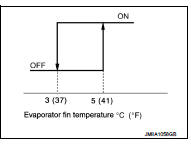
Low Temperature Protection Control
With HR16DE and MR16DDT • When intake sensor detects that evaporator surface temperature is 3°C (37°F) or less, A/C auto amp. requests ECM to turn the compressor OFF, and stops the compressor.
When the air temperature returns to 5°C (41°F) or more, the compressor is activated.
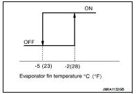
With K9K
• When intake sensor detects that evaporator surface temperature is
−5°C (23°F) or less, A/C auto amp. requests ECM to turn the compressor
OFF, and stops the compressor.
When the air temperature returns to −2°C (28°F) or more, the compressor is activated.
CONTROL BY ECM
Compressor Protection Control at Pressure Malfunction The high-pressure side value that is detected by refrigerant pressure sensor is as per the following state, ECM requests IPDM E/R to turn A/C relay OFF and stop the compressor.
With HR16DE and MR16DDT
• 3.12 MPa (31.82 kg/cm2, 452.4 psi) or more (When the engine speed is less than
1,500 rpm)
• 2.74 MPa (27.95 kg/cm2, 397.3 psi) or more (When the engine speed is 1,500 rpm
or more)
• 0.14 MPa (1.43 kg/cm2, 20.3 psi) or less
With K9K
• 2.8 MPa (28.56 kg/cm2, 406 psi) or more (When the engine speed is less than
1,500 rpm)
• 2.8 MPa (28.56 kg/cm2, 406 psi) or more (When the engine speed is 1,500 rpm or
more)
• 0.12 MPa (1.22 kg/cm2, 17.4 psi) or less
Compressor Oil Circulation Control When the engine starts while the engine coolant temperature is 56°C (133°F) or less, ECM activates the compressor for approximately 6 seconds and circulates the compressor oil once.
Air Conditioning Cut Control When the engine condition is high load, ECM makes the A/C relay to OFF, and stops the compressor. Refer to following.
• HR16DE: EC-476, "AIR CONDITIONING CUT CONTROL : System Description" • MR16DDT: EC-60, "AIR CONDITIONING CUT CONTROL : System Description"
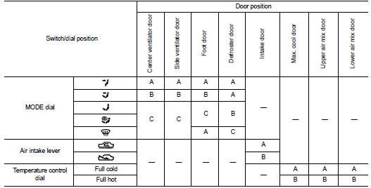
Manual air conditioning system : Door Control
SWITCHES AND THEIR CONTROL FUNCTIONS
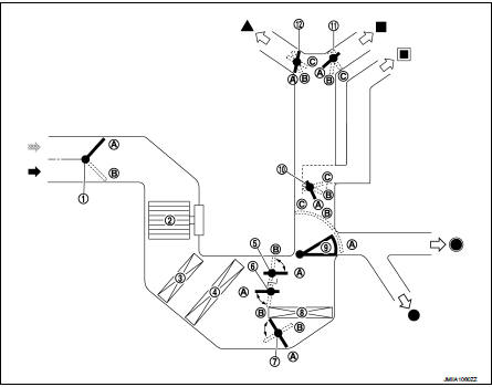
1. Intake door *: With rear foot duct
2. Blower motor
3. Air conditioner filter
4. Evaporator
5. Max. cool door
6. Upper air mix door
7. Lower air mix door
8. Heater core
9. Foot door
10. Side ventilator door
11. Center ventilator door
12. Defroster door
Fresh air intake
Recirculation air
Defroster
Center ventilator
Side ventilator
Foot
Rear foot*
*: With rear foot duct
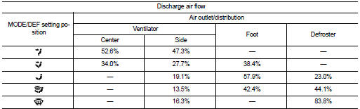
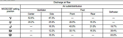
AIR DISTRIBUTION
Without rear foot duct
With rear foot duct
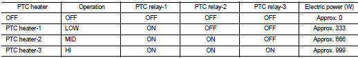
PTC heater control system : System Diagram
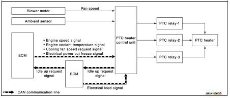
PTC heater control system : System Description
• PTC heater control unit performs PTC relay ON/OFF control based on engine speed, engine coolant temperature, electrical power cut freeze signal (permission signal, retention signal, stop signal), fan speed, ambient temperature, battery voltage, and electrical load signal (high beam request signal, low beam request signal, rear window defogger ON signal, and others).
• When PTC relay turns ON, power supply is supplied to PTC heater. Heating element is heated and air flow temperature is increased. Heating is available for a period of time until engine coolant temperature is increased when engine starts cold in cold climate.
• Idle up request signal is transmitted from PTC heater control unit to ECM while PTC heater operates. Idle speed is increased, warming-up is facilitated, and battery electric power is obtained.
• Electric power supplied to PTC heating element is subject to PTC relay control conditions.
NOTE
:
PTC heater operation depends on ambient temperature and battery voltage. PTC
heater is ON when ambient
temperature is 8°C or less. PTC heater is OFF when ambient temperature is 12°C
or more. PTC heater is ON
when battery voltage is 11.5 V or more. PTC heater is OFF when battery voltage
is 11 V or less.
 Component parts
Manual air conditioning system : Component Part Location
1. BCM
• With Intelligent Key: Refer to BCS-
6, "BODY CONTROL SYSTEM :
Component Parts Location".
• Without Intelligent Ke ...
 Operation
Switch Name and Function
A/C CONTROLLER (A/C CONTROL)
1. MODE dial
2. Fan control dial
3. A/C switch
4. Temperature control dial
5. Intake lever
...
Other materials:
P position warning does not operate
Diagnosis Procedure
1.CHECK DTC WITH BCM, TCM AND COMBINATION METER
Check that DTC is not detected with BCM, TCM and combination meter.
Is the inspection result normal?
YES >> GO TO 2.
NO-1 >> Refer to BCS-67, "DTC Index". (BCM)
NO-2 >> Refer to TM-171, "DT ...
Back door
Exploded View
REMOVAL
1. Back door weather-strip
2. Back door stay
3. Back door stay lower bracket
4. Bumper rubber
5. Back door striker
6. Back door panel
7. Back door hinge
8. Hole cover
A : Center mark
B : Seam
: Do not reuse
: Body grease
Back door assembly
BACK DOOR ASSEMB ...
P1588 G sensor
DTC Logic
DTC DETECTION LOGIC
DTC CONFIRMATION PROCEDURE
CAUTION:
Be careful of the driving speed.
1.PREPARATION BEFORE WORK
If another "DTC CONFIRMATION PROCEDURE" occurs just before, turn ignition
switch OFF and wait for at
least 10 seconds, then perform the next test.
> ...
