Nissan Juke Service and Repair Manual : P183B solenoid power supply
DTC Logic
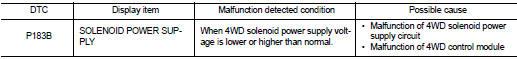
DTC DETECTION LOGIC
DTC CONFIRMATION PROCEDURE
1.PRECONDITIONING
If ŌĆ£DTC CONFIRMATION PROCEDUREŌĆØ has been previously conducted, always turn ignition switch OFF and wait at least 10 seconds before conducting the next test.
>> GO TO 2.
2.DTC REPRODUCTION PROCEDURE
 With CONSULT-III
1. Turn the ignition switch OFF to ON.
2. Perform self-diagnosis for ŌĆ£ALL MODE AWD/4WDŌĆØ.
Is DTC ŌĆ£P183BŌĆØ detected? YES >> Proceed to diagnosis procedure. Refer to DLN-67, "Diagnosis Procedure".
NO >> INSPECTION END
Diagnosis Procedure
1.CHECK 4WD SOLENOID POWER SUPPLY (1)
1. Turn the ignition switch OFF.
2. Disconnect 4WD control module harness connector.
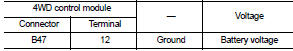
3. Check the voltage between 4WD control module harness connector and ground.
4. Turn the ignition switch OFF to ON.
CAUTION:
Never start the engine.
5. Check the voltage between 4WD control module harness connector and ground.
Is the inspection result normal? YES >> GO TO 3.
NO >> GO TO 2.
2.CHECK 4WD SOLENOID POWER SUPPLY (2)
1. Turn the ignition switch OFF.
2. Check the 10A fuse (#12).
3. Check the harness for open or short between 4WD control module harness connector No.12 and the 10A fuse (#12).
Is the inspection result normal?
YES >> Perform the trouble the diagnosis for power supply circuit. Refer to PG-10, "Wiring Diagram - BATTERY POWER SUPPLY -".
NO >> Repair or replace error-detected parts.
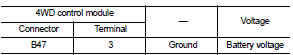
3.CHECK 4WD CONTROL MODULE POWER SUPPLY (1)
1. Turn the ignition switch OFF.
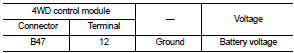
2. Check the voltage between 4WD control module harness connector and ground.
3. Turn the ignition switch ON.
CAUTION:
Never start the engine.
4. Check the voltage between 4WD control module harness connector and ground.
Is the inspection result normal? YES >> GO TO 5.
NO >> GO TO 4.
4.CHECK 4WD CONTROL MODULE POWER SUPPLY (2)
1. Turn the ignition switch OFF.
2. Check the 10A fuse (#3).
3. Check the harness for open or short between 4WD control module harness connector No.3 terminal and 10A (#3).
Is the inspection result normal? YES >> Perform the trouble diagnosis for ignition power supply circuit. Refer to PG-15, "Wiring Diagram - IGNITION POWER SUPPLY -".
NO >> Repair or replace error-detected parts.
5.CHECK 4WD SOLENOID GROUND
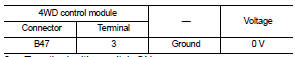
Check the continuity between 4WD control module harness connector and ground.
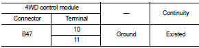
Is the inspection result normal? YES >> GO TO 6.
NO >> Repair or replace the error-detected parts.
6.CHECK TERMINALS AND HARNESS CONNECTORS
1. Check 4WD control module pin terminals for damage or loose connection with harness connector.
2. Check 4WD solenoid pin terminals for damage or loose connection with harness connector.
Is the inspection result normal? YES >> Replace 4WD control module. Refer to DLN-91, "Removal and Installation".
NO >> Repair or replace the error-detected parts.
 P183A coupling temperature sensor right
DTC Logic
DTC DETECTION LOGIC
DTC CONFIRMATION PROCEDURE
1.PRECONDITIONING
If ŌĆ£DTC CONFIRMATION PROCEDUREŌĆØ has been previously conducted, always turn
ignition switch OFF and
wait at least ...
 P183C decel G sensor
DTC Logic
DTC DETECTION LOGIC
DTC CONFIRMATION PROCEDURE
1.PRECONDITIONING
If ŌĆ£DTC CONFIRMATION PROCEDUREŌĆØ has been previously conducted, always turn
ignition switch OFF and
wait at least ...
Other materials:
Oil seal
Valve oil seal
VALVE OIL SEAL : Removal and Installation
REMOVAL
1. Remove camshafts. Refer to EM-191, "Exploded View".
2. Remove valve lifters. Refer to EM-191, "Exploded View".
3. Rotate crankshaft, and set piston whose valve oil seal is to be removed to
TDC. This will p ...
B2098 ignition relay on stuck
Description
The ignition relay integrated in IPDM E/R is operated with ignition switch ON
signal from the ignition switch.
DTC Logic
DTC DETECTION LOGIC
1.PERFORM DTC CONFIRMATION PROCEDURE
1. Turn ignition switch ON.
2. Check DTC in ŌĆ£Self Diagnostic ResultŌĆØ mode of ŌĆ£IPDM E/RŌĆØ usin ...
B2630, B2631 sunload sensor
DTC Logic
DTC DETECTION LOGIC
NOTE:
ŌĆó If DTC is displayed along with DTC U1000, first perform the trouble diagnosis
for DTC U1000. Refer to HAC-
51, "DTC Logic".
ŌĆó If DTC is displayed along with DTC U1010, first perform the trouble diagnosis
for DTC U1010. HAC-52,
"DTC L ...
